
phase control circuit

The phase control circuit is constructed to manage the power flow in AC systems by modulating the waveform based on the desired output. The circuit design includes a triac, which acts as the primary switching component, allowing current to flow when triggered. The U208B integrated circuit serves as the control unit, providing the necessary logic to synchronize the switching with the zero crossings of the AC waveform. This synchronization is crucial as it minimizes electrical noise and reduces stress on the triac, enhancing its lifespan and reliability.
The circuit begins with an AC input, which is then processed by the U208B. The IC monitors the input voltage and generates control signals that dictate when the triac should be turned on or off. By adjusting the timing of these control signals, the circuit can effectively control the amount of power delivered to the load. For instance, delaying the turn-on time results in a reduced power output, which is ideal for applications such as dimming lights or controlling motor speeds.
In addition to its primary function, the U208B incorporates features that provide protection and stability. The internal voltage monitoring ensures that the IC operates within safe limits, preventing damage due to voltage spikes. The built-in current synchronization helps maintain consistent operation even as load conditions change, making the circuit versatile across various applications.
Overall, this phase control circuit design is efficient, cost-effective, and suitable for a wide range of AC load control applications. Its integration of the U208B IC simplifies the design process while enhancing performance, making it an excellent choice for engineers and designers working with AC power control.This is a simple design schematic circuit for phase control circuit. The circuit can be used to control the power delivered to an AC load. The phase control circuit can control the AC waveform, cutting the cycle to give full cycle, half cycle, zero cycle, or somewhere in between. You can say this circuit is similar to a dimmer circuit, but the swi tching is synchronized with the zero crossing of the waveform. This circuit is works using based on IC U208B. This is the figure of the circuit. The benefit of switching the power in zero crossing condition is that the triacs doesn`t suffer power dissipation, thus increasing the overall efficiency. This phase control circuit is suitable for brushed AC motor, heater filament, or incandescent lamps. The IC U208B is designed as a phase control circuit in bipolar technology with internal supply-voltage monitoring.
As the voltage is built up, uncontrolled output pulses are avoided by internal monitoring. Furthermore, it has internal-current and voltage synchronization. It is recommended as a low cost open-loop control. [Schematic diagram source: TEMIC TELEFUNKEN Microelectronic Application Notes] 🔗 External reference
Related Circuits
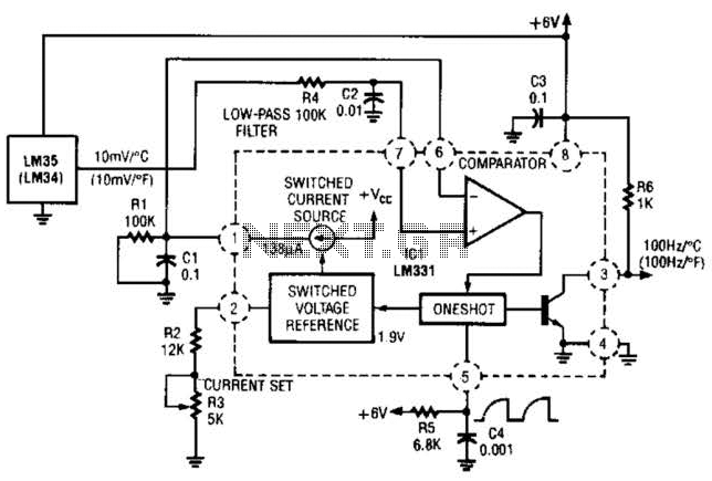
In this circuit, an LM34 or LM35 generates a frequency that is proportional to temperature. The reference current (138) is established through resistor R3. The output can be utilized to drive a display, frequency counter, or other indicating devices...
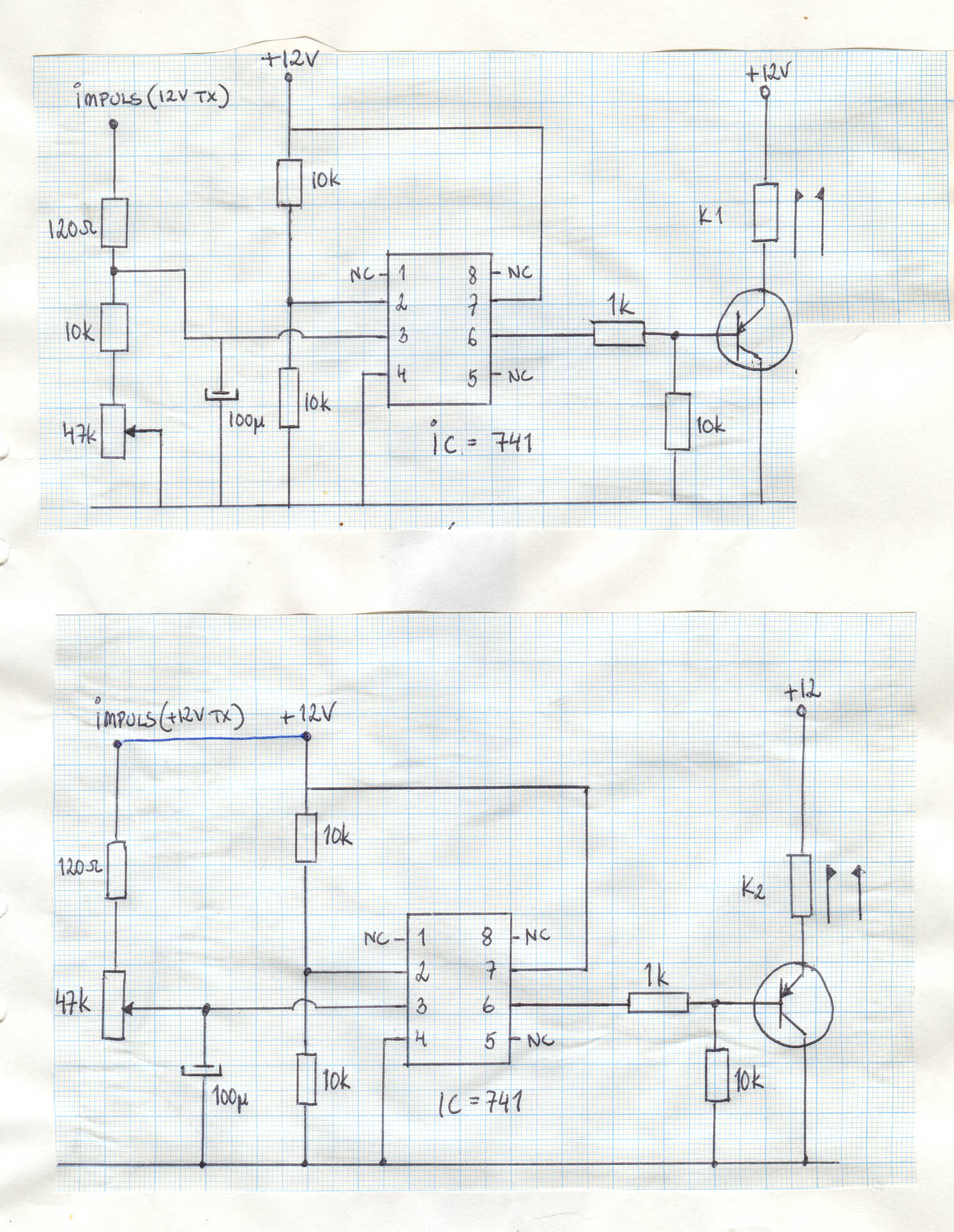
Transistors are configured as a Darlington pair in this circuit. A thermistor is utilized to detect or sense heat. A 12K variable resistor is employed to adjust the activation of the buzzer at the desired temperature. The operation of...
A 12-volt power supply is used to operate a sequencer board that controls external relays for coaxial relays, a preamplifier, and an amplifier. The sequencer board features DIL relays designed to drive these external relays. Although there are more...
The circuit presented is an integrated circuit (IC) controlled emergency light. Its key features include automatic activation of the light during mains failure and a battery charger equipped with overcharge protection. In the absence of mains power, relay RL2...
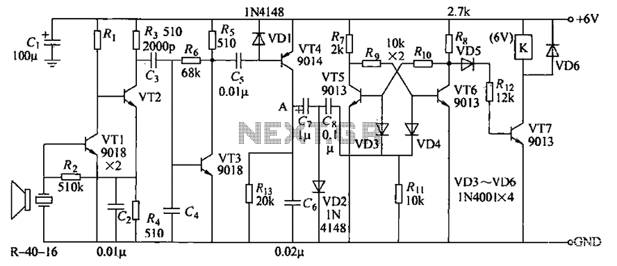
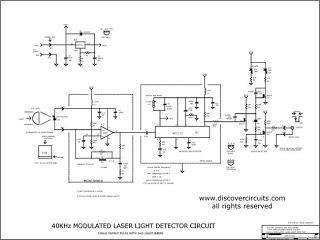
The circuit consists of transistors VT1 through VT7 and other components. Due to the weak signal received from the transmitter, the circuit employs a multi-stage amplifier to enhance the output. This output generates a square wave pulse signal to...
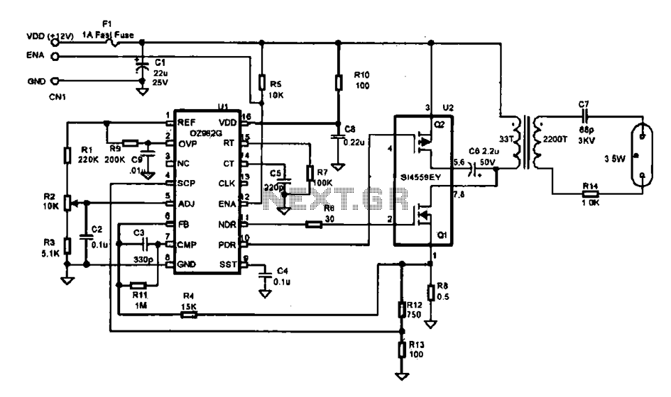
This document describes an efficient inverter control circuit designed for use as an LCD backlight power supply. The circuit is primarily managed by the chip UL (02962G), which interfaces with a driving field-effect transistor (U2), a voltage transformer, the...