
Methods of Monitoring Fan Performance
The integration of fan monitoring systems into electronic designs is crucial for maintaining system integrity and preventing overheating. The Tachometer Output and Fan Performance Sensor (FPS) provide essential feedback regarding fan operation, enabling timely interventions to avoid component damage. The Hall effect sensor's ability to generate a square wave pulse train is fundamental to these monitoring systems, allowing for real-time speed assessment. The adaptability of the output voltage ensures compatibility with diverse electronic systems, catering to specific operational requirements.
In applications where fan performance is critical, the choice between isolated and non-isolated sensor circuits can significantly affect system design. An isolated sensor circuit, while more complex, offers enhanced safety and reliability, especially in environments with varying voltage potentials. Conversely, non-isolated circuits simplify integration but may limit operational flexibility.
The FPS's constant output feature is particularly advantageous for automated systems, facilitating direct connections to alert mechanisms without the need for additional signal conditioning. This capability streamlines the design process, allowing engineers to focus on other critical aspects of the system.
Overall, the monitoring solutions offered by Comair Rotron are essential components in modern electronic systems, ensuring that cooling mechanisms function effectively and reliably, thereby safeguarding against potential failures and associated costs.Today`s electronic systems are in a continuing, evolving design cycle where more smaller, and hotter components are being crammed into tight enclosures. These expensive systems need to remain dependable and reliable. A fan failure may result in other delicate and expensive components failing, causing costly repairs and delays.
The best way to deal with fan failures is to know exactly when a fan fails and moderate the system until repairs can be made. Comair Rotron currently offers two ways to monitor the fans performance. A Tachometer Output is an easy and inexpensive way to monitor the speed at which the fan is running. The customer will need to develop circuitry to read the tachometer signal and determine when the fan has failed to provide adequate cooling.
A Fan Performance Sensor (FPS) has the circuitry internally in the fan to read the tachometer signal and determine if the fan has failed. Both options are further described below. The Tachometer Output is derived from a hall cell that senses the rotating magnetic fields generated by the rotating rotor.
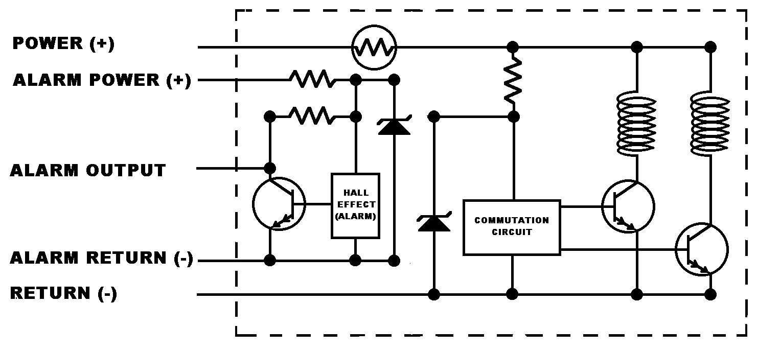
The hall cell emits a square wave pulse train as shown in Figure 1. The square wave has a 50% duty cycle with an amplitude of Vout. On most fan models, the tachometer will have 2 pulses per revolution. A few others will have 1 pulse per revolution. The standard amplitude, shown as Vout is 5V. This voltage level is set internal to the fan. See Figure 2. The customer will need to develop electronic circuitry to monitor the output and detect a failure. The customer may desire a Vout of a different amplitude. Comair Rotron can provide that output up to the value of the input voltage (i. e. , a 24 VDC fan would generate up to 24V square wave on the sensor lead). If the customer wishes to set the output amplitude, Comair Rotron can provide an open collector output. There is no output on the sensor lead until an external pull-up resistance is attached. The value of the resistance will need to be determine so that the current is limited to 15mA. See Figure 3. On most models, the fan is offered with either an isolated or non-isolated sensor circuit. A fan with an isolated sensor would have five lead wires. Two solid colored power leads [Red (+), Black (-)] provide power to the motor windings. There would also be three sensor circuit leads [Red/White (+), Black/White (-), and Blue/White (sensor output)] to power the tachometer and the signal return.
See Figure 4. A fan with a non-isolated sensor would have only three lead wires. Two solid colored motor power leads [Red (+), Black (-), and Blue/White (sensor lead)}. The power for the sensor circuitry is internally derived from the power of the motor windings. An isolated tachometer is typically used where a negative voltage potential is used to power the fan and a positive voltage potential is used for the tachometer monitoring circuitry. The two different voltage potentials have different references to ground return and therefore have to be isolated.
A non-isolated tachometer output is typical and can be found on almost every fan model. The Fan Performance Sensor (FPS), for DC fans, is the second type of sensor signal offered by Comair Rotron. It offers a constant output through the sensor lead. The output is derived from a Hall Cell in the same manner as the Tachometer Output. However, there is additional circuitry internal to the fan to condition the output and provide a constant Vout.
The output can then be hooked directly to an alarm, LED, buzzer, relay, etc, . The output will remain constant until a specified RPM level is reached. At that point, the signal output will change to a different state. The RPM is typically set at a threshold of 1900 RPMs. The FPS version offers several different configurations; which must be selected in order to match the downstream electronics of the customer`s equipment. These options are further discussed below. Open Collector: The sig 🔗 External reference
Related Circuits

The FAN4810 operates as a continuous conduction mode (CCM) power factor correction (PFC) controller. It features an internal safety detection mechanism that prevents circuit malfunction due to component damage. The device has a power-handling capability of up to 1A,...
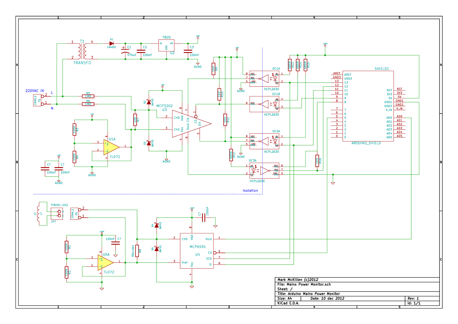
A mains (220-240VAC) power monitoring circuit has been sought for interfacing with an Arduino. While the OpenEnergyMonitor solution employs a transformer for isolation and measurement of mains voltage, it has been noted that the transformer does not couple effectively...
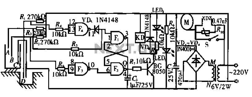
The circuit operates by monitoring the water level in a tank. When the water level falls below a specified point (F), the RS flip-flop (F2) is activated, producing a high Q output that energizes a relay to start the...
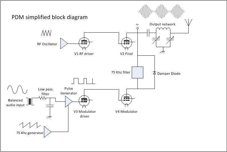
Amplitude Modulation (AM) is the first type of modulation that impressed audio onto a radio frequency (RF) carrier. Before AM, information was transmitted using on/off keying of a continuous wave transmitter, typically through Morse code or similar methods. 1....
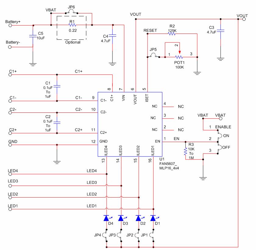
The FAN5607 Evaluation Board is a compact circuit featuring the FAN5607 HMPX in a 4x4 MLP package along with two 4.7 µF capacitors. This setup is designed to deliver stable input and output current for up to four of...
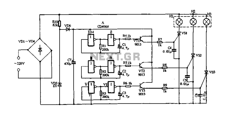
The circuit consists of a bridge diode rectifier formed by diodes VD1 to VD4, which converts 220V AC into pulsating DC. This DC is utilized to power red, green, and blue electric lights (H1 to H3). Additionally, a resistor...