
isolated mains power monitoring arduino
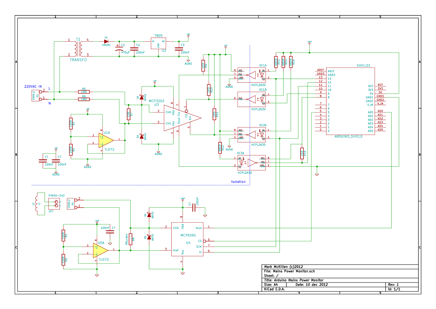
The mains power monitoring circuit is designed to provide accurate measurements of voltage and power usage for applications interfacing with Arduino microcontrollers. The primary component of the circuit is a dual-channel Analog-to-Digital Converter (ADC), which is crucial for digitizing the analog voltage signals derived from the mains supply. The opto-isolation feature ensures that the low-voltage side of the circuit is electrically isolated from the high-voltage mains, thus enhancing safety and protecting the Arduino from potential overvoltage conditions.
The voltage measurement is accomplished through a voltage divider network, which reduces the high mains voltage to a safe level suitable for the ADC input. The choice of resistors in the divider is critical; the revised design employs a 1MΩ resistor for current limiting and a 10KΩ resistor to ensure that the voltage swing on the ADC input is maximized while maintaining the integrity of the measurement. This configuration allows for a peak input voltage of approximately 311V to be scaled down to a range that the ADC can handle without distortion.
The use of a 12-bit ADC (MPC3202) enhances the resolution of the measurements compared to the original 10-bit design. Although the sampling rate is reduced to 100ksps, this is generally sufficient for monitoring applications where high-speed data acquisition is not critical. The design can be simulated using software tools like KiCAD to visualize the circuit's behavior and validate its performance before physical implementation.
In summary, the mains power monitoring circuit provides a robust solution for measuring AC voltage and power consumption, suitable for integration with Arduino platforms. The careful selection of components, particularly the ADC and voltage divider, ensures accurate readings while maintaining safety and reliability in operation.I`ve been looking around for a mains (220-240VAC) power monitoring circuit that I might be able to interface with an Arduino. There is of course the OpenEnergyMonitor solution, but they seem to use a transformer to isolate and measure the mains voltage.
The transformer doesn`t exactly couple to the mains nicely: so the voltage on the secondary side is not a scaled voltage of the input side, the transformer itself will distort the voltage sine wave. Then over the weekend I came across Dave Berkeley`s Project Page, and he has a cool design for mains power usage monitor that does measure the line voltage directly. His Home Energy Monitor uses a dual channel ADC with opto-isolation, nice solution. There is loads of info over at his site, I`ve just changed a few little parts for my version. He uses a 10bit ADC [MPC2003] which I couldn`t get from RS, they were showing back order on the part, so I had a dig around and came up with a 12bit version of the same chip [MPC3202] just have to watch the conversion time, it`s not 200ksps but 100ksps, but I don`t see it being a problem (famous last words!).
So started up KiCAD and got work, then on to RS to get the parts! If you like a PDF of the circuit diagram here you go: Mains Power Monitor Circuit Diagram (rev 1. 0) On Dave`s circuit he has a voltage divider that I couldn`t make sense of, it looks like he has 100K current limiting resisters on the two input lines and a divider made up from one of these and a 270R. The simulation on this only gave a 2. 08 -> 2. 92 volt swing on the ADC, given a 311V peek to peek AC input [which is 220VAC * sqt(2)]. I`ve used 1M0 on the current limiting and a divider of 1M0 and 10K, which give a little more input to the ADC.
🔗 External reference
Related Circuits
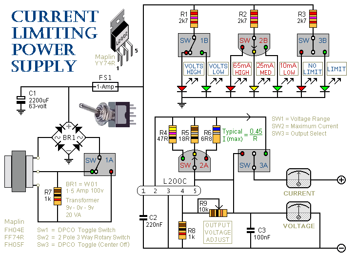
This is a 1-amp variable-voltage power supply unit (PSU) that adjusts the output voltage from approximately 3V to 24V. It features a current limiting option, which is particularly useful for initial power-ups or soak-testing equipment. SW3 acts as the...
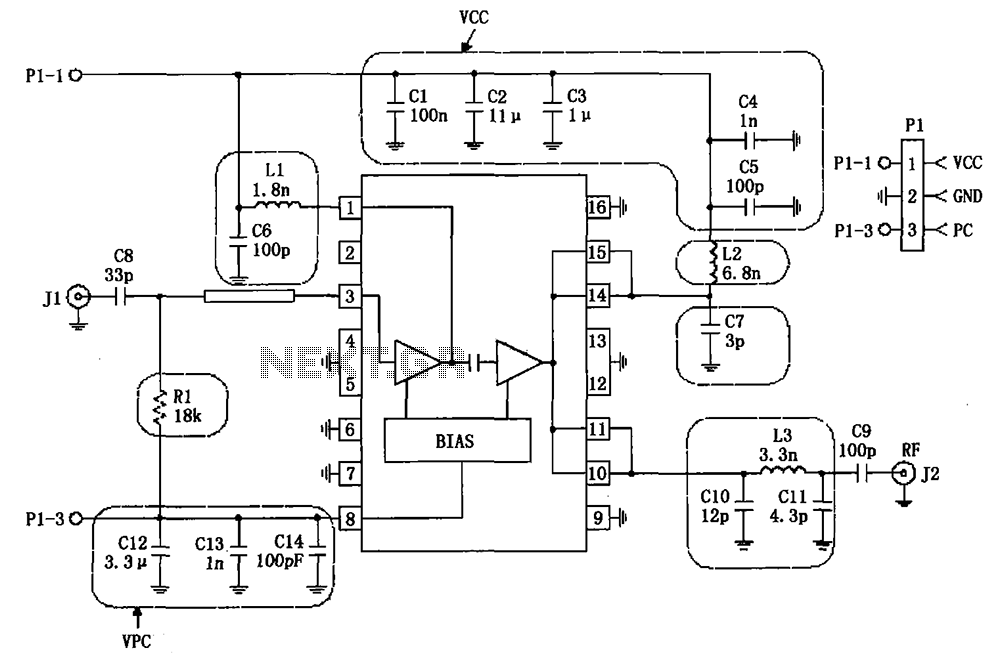
The RF2132 linear power amplifier circuit is depicted in the provided figure. A radio frequency (RF) signal enters through input pin 3 and is processed via a preamplifier. The final stage of the amplifier outputs a gain of 10....
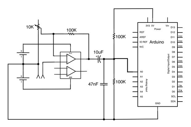
This Arduino-powered vocal effects box pitch shifts and distorts incoming audio signals to produce a wide variety of vocal effects. This project serves as an experiment with real-time digital signal processing using Arduino. It samples an incoming microphone signal...
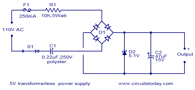
The circuit diagram illustrates a 5V transformerless power supply utilizing minimal components. The operation of this circuit is straightforward. Resistor R1 serves as a current limiter, while bridge D1 rectifies the mains voltage. The Zener diode regulates the output...
This circuit is intended to indicate the power output level of any audio amplifier. It is simple, portable, and displays three power levels that can be set to any desired value. IC1A is the input buffer, feeding 3 voltage...
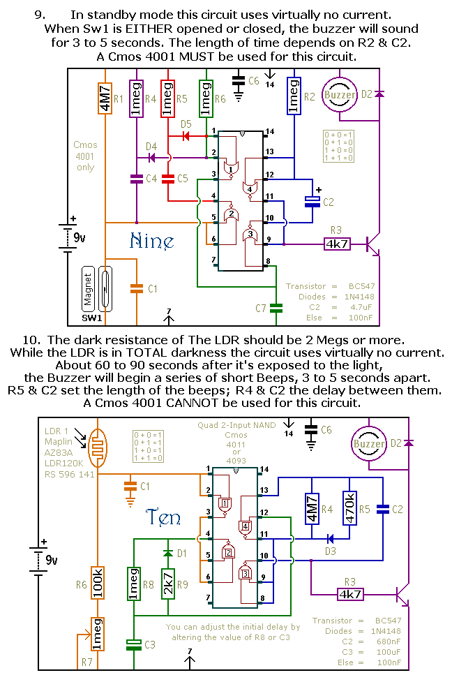
This document outlines a selection of small self-contained alarm circuits. Each alarm's main features are detailed on the circuit diagram. They are designed to have a very low standby current, making them suitable for battery operation. Each pair of...