
Methods for generating Amplitude Modulation
The design of amplitude modulation systems encompasses various modulation techniques, each with distinct advantages and limitations. Low-level modulation is favored for its simplicity, making it ideal for mobile applications, although it suffers from linearity issues. Doherty modulation, on the other hand, enhances efficiency by utilizing a combination of tubes that optimally manage output impedance during modulation, thus improving power utilization. High-level modulation systems stand out for their ability to deliver higher power levels and superior audio fidelity, although they necessitate larger physical footprints and more complex setups. Ampliphase modulation presents a compact solution with a unique phase relationship approach but requires meticulous tuning to avoid distortion. PDM and PWM methods leverage advanced encoding techniques to achieve efficient power management, particularly in solid-state designs, while Direct Digital Synthesis represents a modern evolution in transmitter technology, facilitating precise audio sampling and modulation at high frequencies. Each of these methods contributes to the robustness and versatility of RF transmission systems, catering to diverse operational requirements and technological advancements in the field of electronics engineering.Amplitude Modulation (AKA AM) was the first modulation type to impress audio on an RF carrier. Prior to this, information was transmitted via on/off keying of a continuous wave transmitter using Morse code or some equivalent. 1. Low level modulation. The modulation is developed in the first stage RF section, then amplified by subsequent stages to full power. Simple and easy to implement, especially for mobile transmitters and SSB installations. Disadvantages come from the need for linear amplification through all the stages requiring class A or AB amplifiers and does not reproduce wide band AM well. 2. Doherty modulation. William Doherty came up with an ingenious way to use a low level linear modulator with good to excellent efficiency.
Under full carrier, no modulation conditions, the carrier tube is generating the RF carrier and the peak tube is mostly cut off (very little current). When modulation is applied, the peak tube then begins to conduct, the output of this tube is combined with the output of the carrier tube through a 90 ° LC network, which is the same as 1/4 wave length transmission line.
The effect of this is to lower the output impedance, thus allowing the carrier tube to modulate 100 percent. 3. High level or plate modulation. The RF and Audio sections are developed separately with in the transmitter, then combined in the final stage of the transmitter.
Older systems used a modulation transformer. Advantages are all the amplifiers can be run class C or greater, which reduced electrical consumption and power supply requirements. Much higher power levels are achievable with this design. These transmitters also reproduce wide band audio much better than low level modulated units. They are also extremely rugged. Disadvantages are the system requires large audio section and they take up greater area and are not as efficient as later modulation methods.
4. Ampliphase. A phase modulated system developed by RCA where the transmitter developed two RF signals in the final, 135 degrees apart. To modulate the signal, the phase relationship between the carriers is varied, more toward 180 degrees would be a negative peak and more toward 90 degrees a positive peak.
These transmitters required less space and where more efficient than traditional plate modulated transmitters. They required careful set up and tune up to reduce distortion and somewhat unfairly earned the name amplifuzz from some engineers.
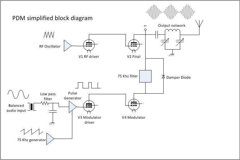
5. PDM or PWM. This is also a high level modulation scheme, but with some slight variations. The carrier power level and modulation levels are set by a PDM encoder card. In Harris transmitters, the PDM frequency was 75 KHz. The carrier is set by the amplitude of the PDM wave form, the modulation is determined by the duration of the pulse. PDM transmitters require power supply voltages about twice the voltage of a standard high level plate modulated transmitters.
They also require a damper diode to conduct to conduct the B+ voltage to back to the power supply during negative peaks, otherwise the PA voltage will attempt to rise to infinity. I have found the damper diode to be the weak link in a tube type PDM transmitter. Solid state transmitters also use this design with either MOSFETs or BJT, which are then combined in parallel to generate the required output power.
This is most often called Class E or something similar. In that system, each pair of modulator MOSFETs has it`s own fast acting damper diode, usually protected by a fuse. 6. Direct Digital Synthesis. This is a patented design from Harris broadcast used in their DX series transmitters. The incoming audio is sampled at either the carrier frequency or 1/2 the carrier frequency depending on where in the band the station falls.
The solid state PA modules are then switched on and off at the carrier frequency with the audio levels imposed on the carrier information. The explanation is simple, the applicatio 🔗 External reference
Related Circuits
Pulse Width Modulation (PWM) is a highly efficient control scheme utilized to regulate the flow of power through various electronic devices. It is commonly found in switched-mode power supplies, LED dimming circuits, and variable speed motor controls, among other...
Figure 7-2 illustrates the FSK (Frequency Shift Keying) signal demodulation circuit, which is built using a digital phase-locked loop. This circuit features two oscillators operating at distinct frequencies: crystal oscillator X with a frequency of 983.04 kHz and crystal...
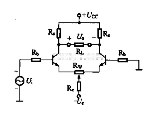
Differential amplifier circuit with four connection methods and characteristics for comparison. The circuit exhibits magnification with a single tube when symmetrical. Additionally, CMRR (Common Mode Rejection Ratio) is adapted from single-ended input to a double-ended output. The differential amplifier is...
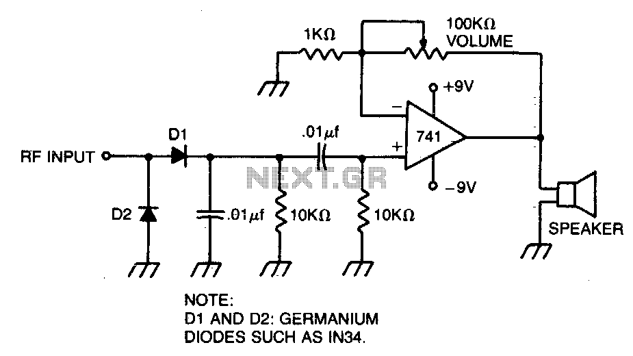
A broad-tuned receiver demodulates the RF signal picked up by a loosely coupled wire placed near the transmitting antenna. The broad-tuned receiver operates by utilizing a loosely coupled wire antenna, which is strategically positioned in proximity to the transmitting antenna....

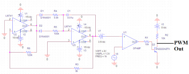
The simple pulse width modulation circuit is illustrated in the figure. It utilizes an operational amplifier to create a multivibrator, resulting in a symmetrical oscillation output signal with a duty cycle of 50%. By adjusting the external threshold voltage,...
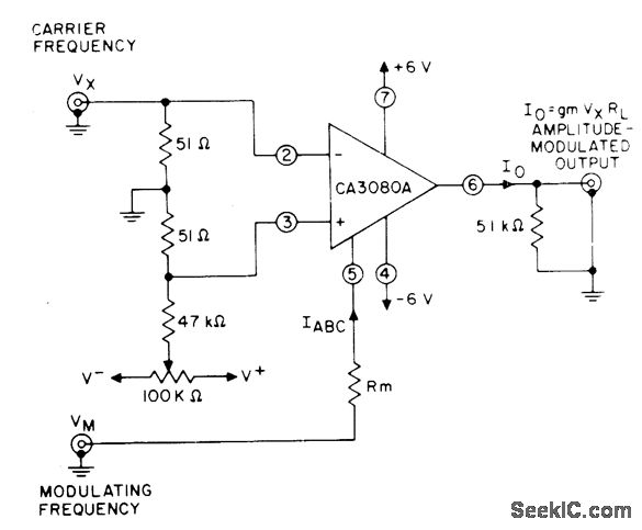
The circuit utilizes a controlled variation of amplifier bias current (IABC) in the CA3080A variable operational amplifier to achieve effective gain control of the signal. Changes in the amplitude of the modulating voltage (Vm) alter the bias current through...