
Metronome
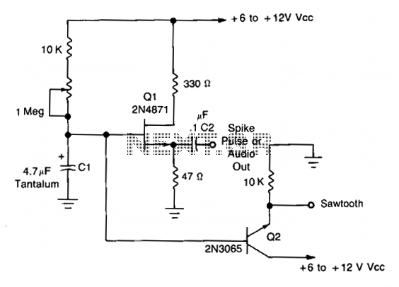
The oscillator circuit primarily consists of the 2N4871 Unijunction Transistor (UJT), which serves as the core component for pulse generation. The UJT operates by utilizing its unique characteristics, which allow it to switch on and off rapidly, creating the desired oscillation frequency. The frequency of oscillation is determined by the values of the resistors and capacitors connected to the UJT, specifically affecting the timing intervals for charging and discharging.
In this configuration, C2 acts as a coupling capacitor, allowing the spike generated by the UJT to be transmitted to subsequent stages or components in the circuit. The sawtooth waveform observed at the emitter of Q2 is indicative of the charging and discharging cycle of the capacitor connected to the emitter, which results in a linear ramp-up followed by a sharp drop, characteristic of sawtooth signals.
The amplitude of the sawtooth waveform, approximately 2-3 V peak-to-peak, is influenced by the supply voltage (Vcc). As Vcc increases, the peak-to-peak voltage of the sawtooth waveform may also increase, provided the circuit components are rated for the higher voltage levels.
Overall, this oscillator design is suitable for low-frequency applications where simple pulse generation is required, such as in timing circuits, signal modulation, or as a basic waveform generator for testing purposes. The simplicity of the circuit allows for easy implementation and adjustment, making it a valuable tool in various electronic applications.This simple oscillator uses a 2N4871 UJT to give pulses from 0.2 to about 20 Hz. A spike is available at C2, a sawtooth at the emitter of Q2 of about 2-3 V p-p, depending on Vcc. 🔗 External reference
Related Circuits
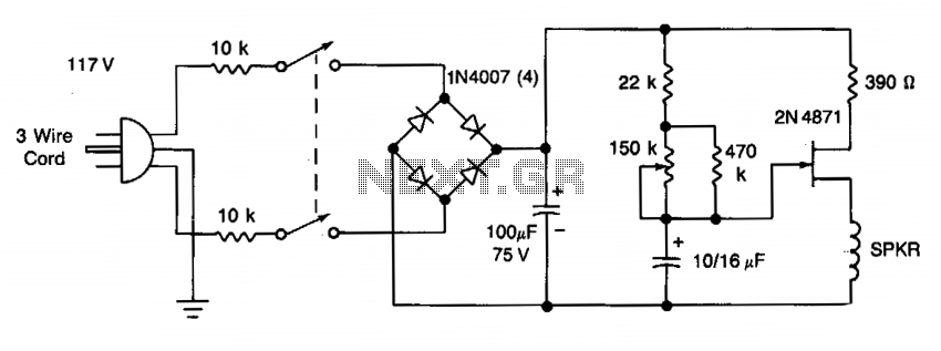
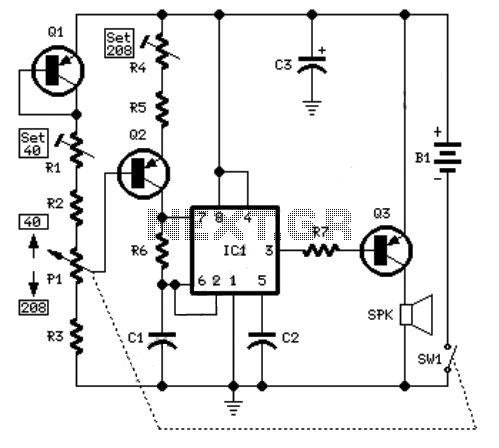
The frequency of the UJT oscillator is determined by the 100 µF capacitor and the effective resistance of the 22 Ω and 470 Ω resistors, along with a potentiometer. The rate can be varied from 42 to 208 beats...

Metronome is an electronic device that keeps rhythm by making regulated clicking sounds, device used to keep the beat while playing a musical instrument. The circuit is an old design to build, but you will find it useful. The metronome...
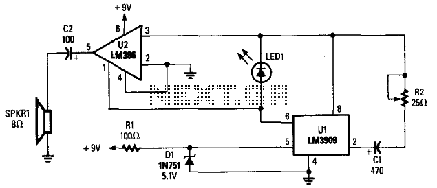
The LM3909 is configured such that the frequency of oscillation relies on a single RC timing circuit, which includes capacitor C1 and resistor R2. LED1 discharges capacitor C1, and the resulting pulse is directed to both pin 3 and...

This is a simple circuit utilizing the NE555 integrated circuit (IC) designed to generate metronomes. Such a circuit is particularly beneficial for music learners. The configuration operates as an astable multivibrator centered around the NE555. The output frequency is...
Precision Frequency generator 1 to 999 Hz Precision Metronome 1 to 999 beats per minute. CMos IC1 and IC2B quad AND gate form a 2.4576 MHz crystal oscillator plus a 2400 times divider. IC3A provides further division by 16,...
An example of an electronic metronome schematic is presented. The electronic metronome is popular due to its simplicity and compact size. The electronic metronome schematic typically consists of several key components that work together to produce a rhythmic sound at...