
NE 555 Electronic Metronome Electrical
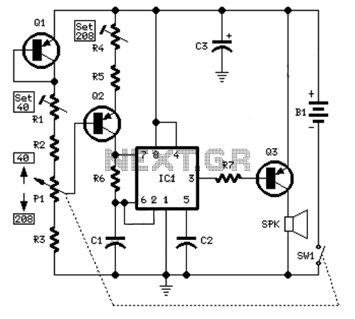
The electronic metronome schematic typically consists of several key components that work together to produce a rhythmic sound at set intervals. The core of the metronome is usually a microcontroller or an integrated circuit (IC) that generates a clock signal. This clock signal determines the tempo, which can often be adjusted by the user.
In addition to the microcontroller, the schematic may include passive components such as resistors and capacitors, which are used to shape the waveform of the output signal. A piezoelectric speaker or a small audio transducer is commonly employed to produce the audible ticks or beats that signify the tempo.
Power supply considerations are also crucial in the design, with the circuit typically powered by batteries or a DC power supply. Voltage regulators may be included to ensure stable operation of the microcontroller and other components.
Furthermore, user interface elements such as buttons for tempo adjustment and LEDs for visual feedback may be integrated into the schematic. These components enhance the functionality of the metronome, allowing musicians to easily set their desired tempo and receive visual cues alongside auditory signals.
Overall, the electronic metronome schematic exemplifies a straightforward yet effective design that serves the fundamental purpose of providing a consistent tempo for practice and performance.Here is one example of the electronic metronome schematic. electronic metronome is very popular since it can be very simple, compact/small, .. 🔗 External reference
Related Circuits
The power supply has been simplified. Power transformers and rectifiers have been omitted, and some components from the MOSFET voltage regulator circuits have been removed, including 1N5242 zener diodes between the source and gate and 10k resistors in series...
This antenna selector circuit diagram electronic project is constructed using standard electronic components and facilitates the switching between two FM antennas through a logic signal. The gates IC1b and IC1a manage the switching and interface between the required logic...
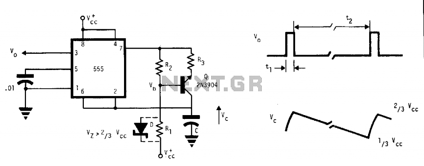
This free-running multivibrator utilizes an external current sink to discharge the timing capacitor, C. As a result, the interval can easily be 1000 times the pulse duration, t1, which defines a positive output. The voltage across the capacitor, V,...

A simple 16-volt switching power supply circuit can be constructed using the provided diagram, which is based on the MAX668 constant-frequency, pulse-width modulating (PWM), current-mode DC-DC controller. This integrated circuit is designed for a wide range of DC-DC conversion...
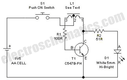
This simple LED driver circuit allows the operation of up to seven LEDs using a single NiMH (Nickel Metal Hydride) AA cell. The circuit generates voltage pulses. The LED driver circuit is designed to efficiently power multiple LEDs while maintaining...
The sections available in this datasheet cover general design considerations for the 555 timer, frequently asked application questions (FAQ), design formulas, and examples of innovative applications. Examples of applications include a Missing Pulse Detector, Pulse Width Modulation (PWM), Tone...