
Metronome generator circuit

The NE555 timer is a versatile component widely used in various timing applications. In this metronome circuit, it functions in astable mode, continuously oscillating between high and low states to produce a square wave output. The frequency of this output is crucial for generating a consistent beat, which is essential for practice in music.
The resistors R1 and R2, along with the capacitor C1, set the timing interval of the oscillation. The frequency (f) of the output signal can be calculated using the formula:
\[ f = \frac{1.44}{(R1 + 2R2) \cdot C1} \]
Where:
- R1 is connected between the discharge pin (pin 7) and the supply voltage (Vcc).
- R2 is connected from the discharge pin (pin 7) to the threshold pin (pin 6).
- C1 is connected from the threshold pin (pin 6) to ground.
In this configuration, the output frequency can be adjusted by varying the values of R1, R2, and C1, allowing users to set the metronome to their desired tempo.
Additionally, a speaker or piezo buzzer can be connected to the output pin (pin 3) of the NE555 to convert the electrical signal into audible sound. A simple low-pass filter may be integrated to smooth out the signal if necessary, enhancing the sound quality.
This metronome circuit can be powered by a standard DC power supply, typically in the range of 5V to 15V, making it suitable for various applications. The simplicity of the circuit and the low cost of components make it an excellent project for beginners in electronics and music education.Here is a simple circuit using IC NE555 that can be used to generate metronomes. Such a circuit is very useful to those who learns music. The circuit is nothing but an astable multivibrator wired around NE555. The components R1, R2&C1 determines the output frequency. 🔗 External reference
Related Circuits
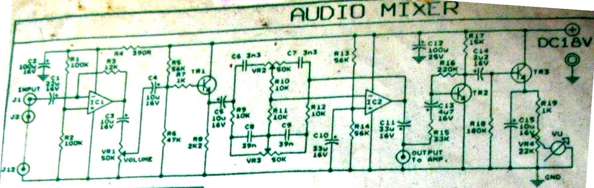
This is audio mixer circuit. The circuit is for one channel input, if you need, for example 5 channel mixer, then you need to build 5 similar circuits. The audio mixer circuit described is designed to handle a single channel...
This document describes a 100 Watt inverter circuit that utilizes a minimal number of components. The circuit employs the CD 4047 integrated circuit (IC) from Texas Instruments to generate 100 Hz pulses, along with four 2N3055 transistors that drive...
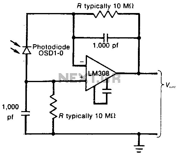
This circuit employs a low-input-bias operational amplifier (op amp) to provide a stable DC indication of light levels. To decrease the sensitivity of the circuit to light, the resistor Rl can be reduced, although it should not be set...
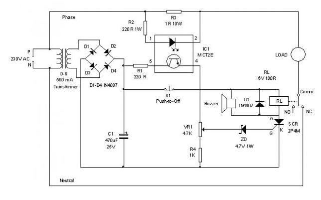
An electronic circuit breaker is designed to detect overload conditions and disconnect power when the load exceeds a predetermined threshold. This circuit is particularly suitable for safeguarding Uninterruptible Power Supply (UPS) devices, such as inverters. The electronic circuit breaker operates...
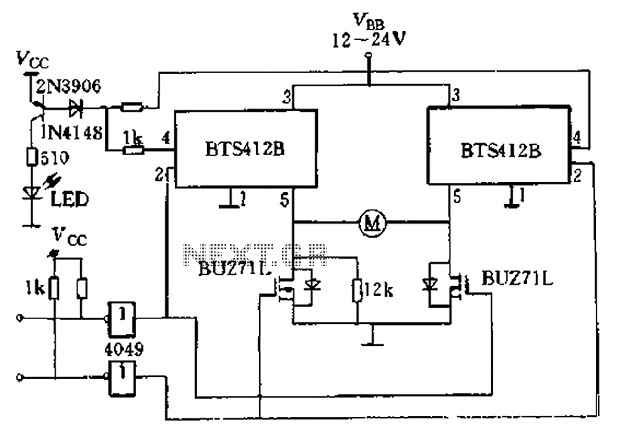
The BTS412B functions as two high-side power MOSFET switches, while two BU271L (50V, Zhang 1n) serve as low-side switches, forming a bi-directional H-bridge DC motor drive circuit. This configuration is designed for electrical automatic door systems, capable of handling...
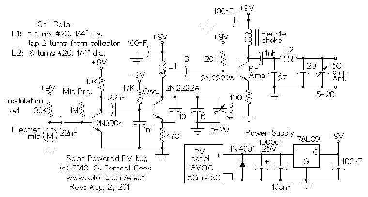
Here are some utility circuits for use with the Ramsey FM10a, and other small FM stereo transmitter kits. This information may be helpful for setting up a micro powered FM radio station. The FM10a and similar kits tend to...