
Mettle Detector circuit with Ic4093
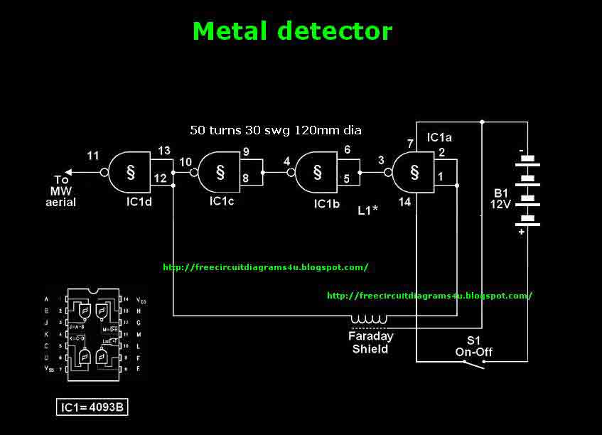
The described circuit is a metal detection system that utilizes a Faraday shield to minimize interference from external electromagnetic fields. The Faraday shield is created by wrapping tin foil around the coil, which serves to isolate the sensitive components of the circuit from external noise, ensuring that the detection of metal objects is more accurate.
The circuit operates on a 12V power supply, which is a common voltage level for many electronic applications, providing sufficient power for the operation of the components involved. The design includes an integrated circuit (IC1d) that plays a crucial role in processing the signals detected by the coil. Specifically, pin 11 of IC1d must be connected to a medium wave (MW) radio aerial. This connection allows the circuit to utilize the radio's ability to pick up electromagnetic waves, which are generated when metal objects are present in proximity to the coil.
The coil itself is constructed from 50 turns of 22 AWG (American Wire Gauge) or 30 SWG (Standard Wire Gauge) enamelled copper wire, which has a diameter of 0.315 mm. This specific wire gauge is chosen for its balance between flexibility and conductivity, enabling effective signal generation and reception. The coil is wound around a former measuring 4.7 inches (120 mm) in diameter, which helps maintain the shape and structure of the coil during operation.
Once the coil is assembled and the Faraday shield is in place, insulation tape is used to secure the components, providing additional protection against environmental factors and ensuring the integrity of the circuit. To operate the metal detection circuit, the user must tune their MW radio until a whistle sound is heard, indicating that the circuit is successfully detecting metal objects nearby.
Overall, this circuit represents a practical application of electromagnetic principles to create a simple yet effective metal detection system, suitable for hobbyists and educational purposes.This circuit needs a a Faraday shield, which is connected to 0V.To make this one wrap a tin foil around the coil.and connect to 0v.Then you can use this circuit for find metal.Tune your mw radio until whistle sound comes. Note # This circuit operates with 12V power supply # IC1d pin 11 needs to be attached to a MW radio aerial, or should be wrapped around the radio # The prototype used 50 turns of 22 awg/30 swg (0.315 mm) enamelled copper wire, wound on a 4.7"/120 mm former. This was then wrapped in insulation tape. 🔗 External reference
Related Circuits

This circuit is a touch switch circuit, similar to a touch door alarm. It utilizes a 555 timer as the core component of the touch switch circuit. The operation begins when the plate is touched, triggering the 555 timer....
The gate-source voltage required to bias the transistor into the linear region can range from 0.25V to 8V, resulting in a potential variation of 7.75V down to a minimal 0.4V for the transistor and load when used with a...
Video-DVM is a very cheap DVM that shows how an output as complex as a videocomposite signal can be generated entirely in software: two I/O pins and three resistors are all the hardware required. Connected to any TV set...
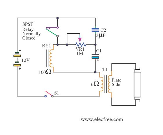
This is a flashing blink circuit designed for 12V applications. It utilizes a small-sized fluorescent lamp and operates through a relay that modifies the circuit from DC to AC. The flashing blink circuit operates at a voltage of 12V, making...
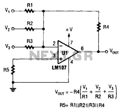
The output of Ul is the sum of Vv, multiplied by the ratio of Rx to Rv, RJRV, and respectively. Resistors R1, R2, and R3 are selected as required for individual gains. Additionally, R4 influences the gain of all...
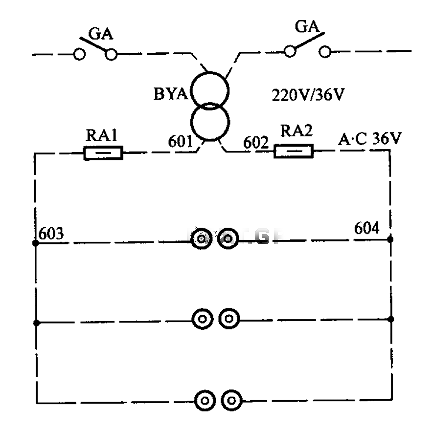
APM-81 lift includes the main circuit, safety circuit, and brake circuit. The APM-81 lift system is designed with a comprehensive electrical architecture that integrates a main circuit, a safety circuit, and a brake circuit, ensuring reliable operation and enhanced safety...
Warning: include(partials/cookie-banner.php): Failed to open stream: Permission denied in /var/www/html/nextgr/view-circuit.php on line 713
Warning: include(): Failed opening 'partials/cookie-banner.php' for inclusion (include_path='.:/usr/share/php') in /var/www/html/nextgr/view-circuit.php on line 713