
fet amp circuit
The circuit in question utilizes a field-effect transistor (FET) that requires precise gate-source voltage (Vgs) to operate effectively within its linear region. The specified Vgs range of 0.25V to 8V indicates a significant variation in performance based on the specific characteristics of the FET used. When paired with an 8.4V NiCad PP3 battery, the operational voltage across the transistor and load can fluctuate dramatically, highlighting the importance of selecting high-quality FETs. The recommendation to purchase additional FETs allows for the elimination of subpar components, ensuring reliable circuit performance.
Temperature stability of the Vgs parameter is crucial for consistent operation. Although variations in temperature can affect electronic components, the FETs in this application are expected to maintain their characteristics, thereby minimizing performance fluctuations. This stability is particularly important in applications where precision is required, as the cost implications of selecting appropriately graded FETs can be a concern in large-scale manufacturing.
To optimize the circuit's performance, utilizing a higher power supply voltage is advised. This approach not only enhances the headroom for the FET but also allows for adjustments to the resistor values, specifically R2 and R3, which would need to be doubled to accommodate the increased voltage. The necessity of two batteries to achieve a suitable operating voltage raises concerns about design efficiency and manufacturing practices, particularly if the FETs are not graded for Vgs.
In practice, verifying the quality of the FET can be accomplished by measuring the drain-source voltage (Vds) and source voltage (Vs) while the circuit is operational. An ideal scenario would yield approximately 2.5V at the source and 6V at the drain, ensuring that the FET operates within its linear region and delivers the expected performance. This measurement is a critical step in the validation process, ensuring that the selected FET meets the design requirements and operates effectively within the specified parameters.The gate-source voltage needed to bias the transistor into the linear region can vary between 0. 25V and 8V, which leaves a good 7. 75V down to a hopeless 0. 4V for the transistor and load if used with a typical NiCad 8. 4V PP3 You`ll have to get more FETs than you need and throw out the dogs. It`s easy enough to test, and this parameter is a given for a particular device it doesn`t age of change greatly with temperature. Design manuals get all sniffy about that sort of thing because selecting FETs obviously adds to the cost if you are mass producing something. That`s not the case here, and there`s just no way to cope with a manufacturing tolerance which can throw more than 90% of the battery voltage away in variations in manufacture without screening the bad `uns.
Ideally you`d run the FET from a higher power supply voltgae, like two batteries in series and perhaps double the values of R2 and R3, but it would be a shame to have to use two batteres just because the manufacturers couldn`t be bothered to grade by Vgs. You can tell if you have a good `un by measuring the voltage at the drain and source of the FET in circuit.
Ideally you would like Vs to be about 2. 5V and Vd to be about 6V (assuming a 8. 4V Nicad PP3) 🔗 External reference
Related Circuits
There are two regulator circuits that utilize the L200 integrated circuit from SGS-Thomson to regulate voltage and current. In circuit Fig. 1, the output voltage can be adjusted using the variable resistor RV1. In Fig. 2, both output voltage...
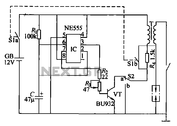
This paragraph describes an easy car alarm circuit that utilizes fewer components and is simple to produce. The circuit consists of an automobile anti-theft alarm system based on the NE555 timer, a power switch (VT), and a switch (S2),...
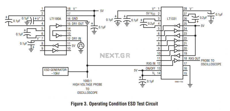
The machine model, commonly used for ESD testing in Japan, is a more severe ESD test. This model simulates metallic contact between the device under test and a charged body. The source capacitor is 200pF with no limiting resistor....
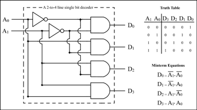
The Encoder and Decoder are different types of combinational circuits used to convert binary information to decimal, octal, and hexadecimal formats, and vice versa. A decoder is a combinational circuit that converts n-bit binary information into 2^n unique outputs....

This schematic represents a simple fluorescent lamp driver circuit utilizing two transistors. The circuit employs capacitive ballasting to drive an 8 W standard fluorescent tube efficiently. The two transistors (2SC 1983) and their associated components create an oscillator operating...
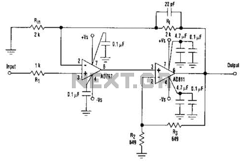
An ultra-low-noise, low-distortion operational amplifier, the AD797, is combined with the ADS 11 operational amplifier, which provides high bandwidth and a 100-mA output drive capability. This composite amplifier circuit is effective for driving high-resolution ADCs and ATE systems. The...