
40 Watt Fluorescent Lamps Diagram Schematics

The circuit operates by first establishing a steady state in which the fluorescent tube is prepped for operation. The continuous supply of electricity ensures that the electrodes remain active, facilitating the ionization of the gas within the tube. The multivibrator generates a square wave signal that is rectified to provide a stable DC voltage, which is crucial for maintaining the flicker frequency of the lamp. The adjustment of the potentiometer (P1) allows for fine-tuning of this frequency, enabling variations in brightness.
Transistor T3 plays a pivotal role in amplifying the control signal, which is necessary to manage the triac's switching behavior. The triac serves as a switch that controls the current flow through the fluorescent tube, allowing it to light up when triggered. The interaction between the pulses from T3 and the capacitor C3 ensures that the thyristor Th1 is activated at the appropriate moment, creating a short circuit that generates the high voltage needed for ignition.
The high voltage generated is essential for starting the fluorescent tube, as it initiates the ionization process within the tube, allowing it to reach a state of luminescence. The design includes careful consideration of insulation and wire management to prevent any unintended electrical contacts, which could lead to circuit failure or safety hazards. The outputs at terminals J8 and J9 provide access for further connections or testing, ensuring the circuit can be integrated into larger systems or modified as needed.
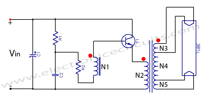
Overall, this circuit exemplifies a well-structured approach to fluorescent lamp operation, incorporating essential components for voltage regulation, signal amplification, and safety measures to ensure reliable performance.This is a Circuits of fluorescent lamp with a power of 40 Watt - The ambit works abundant like the aboriginal Strobos. except that a beaming tube is used. Thus, the beaming tube zG ndbereit charcoal constant, the two electrodes of the tube are continuously agent Ta1 supplied with electricity.
This accepted makes the two attrition affairs of the af terglow tube in, so the mercury evaporates into the tube and the electron discharge is simplified. Ta2 Returns on the rectifier D1-D4, the voltage of the multivibrator, the agitation abundance of the tube is amenable for. The acceleration of the AMV is with potentiometer P1 set. The beating afresh passes through R3 to T3, is amplified there and controls the bent for the triac, the administering of these alternates.
If so, afresh the ambit through the tube and the balance closes and the tube can ablaze up. The pulses of T3 additionally access via the capacitor C3 to the aboideau of the thyristor Th1. Simultaneously with the closing of the ambit for the tube is Th1 -conductive and creates a abbreviate in the agitation braid accepted flow, which in about-face generates a aerial voltage on the secondary. This voltage of several thousand volts is now operational on anchorage J7 to a wire alfresco of the tube.
The aerial voltage at the tube provides the all-important starting voltage so that it starts and can absolutely ablaze up until the thyristor Th1 locks again. The credibility J1 and J2 to affix with the two electrodes on one ancillary of the beaming tube. The credibility J3 and J4, affix with the electrodes on the added side. Now amplitude a attenuate insulated! Wire forth the tube and cement it eg. Scotch band firmly. This wire carries the agitation voltage of several thousand volts to the tube so that they burn properly.
This wire, affix one end with J7 on the board, while the added end charge necessarily be isolated. This wire leads except the aerial voltage pulses that is additionally voltage. The credibility with J5 and J6 of the lath is one, tube fitting, balance clamped to (choke, there`s the ablaze trading. ) Finally there is the voltage at J8 and J9. Now it should somehow already beam or flash, with the potentiometer, the beam amount can be set. 🔗 External reference
Related Circuits

The circuit is based on four integrated circuits: TL072, TL074, MN3101, and MN3004, which produce four output channels for surround audio, specifically targeting center, rear, front right, and front left audio. It is a compact amplifier capable of delivering...
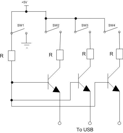
Four switches will be connected to a USB joystick board. The USB board has +5V and ground connections and emulates a button press. The circuit involves interfacing four mechanical switches with a USB joystick interface. The USB joystick board typically...
Fluorescent tube light circuit of an inverter that uses a single transistor and a single transformer. This type of inverter can be made in various configurations. The fluorescent tube light circuit described utilizes a basic inverter design that incorporates a...

This is a compact, easy-to-build amplifier that utilizes a single integrated circuit (IC) to deliver 40 watts of audio power. It is well-suited for amplifying audio signals from devices such as mobile CD players or iPods. The integrated circuit...
This is a low-cost 150-watt amplifier circuit with a diagram and schematic design utilizing two Darlington power transistors, TIP142 and TIP147. The 150-watt amplifier circuit is designed to provide high power output while maintaining cost efficiency, making it suitable for...
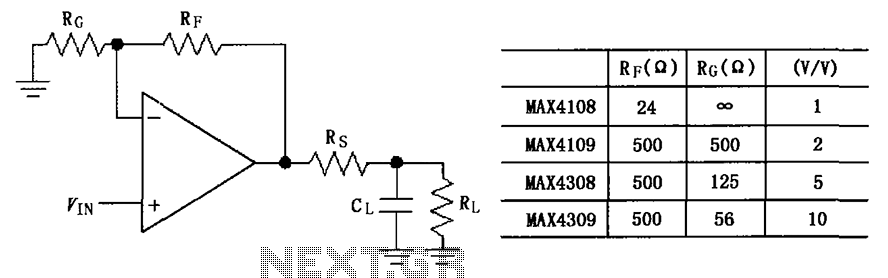
The circuit depicted in the figure employs the MAX4108/4109/4308/4309 operational amplifiers with a capacitive load driving circuit isolation resistor (Rs). While the MAX4108/4109/4308/4309 exhibits excellent AC characteristics, it is not optimized for driving high-load electrical resistances. A significant reactive...