
MFOS Ten Step Analog Sequencer
The core component of the sequencer is U1, a CD4017B CMOS Decade Counter with ten decoded outputs. This chip features ten outputs (0 through 9), which sequentially go high while the others remain low when the clock input transitions from low to high and the clock enable input is low. In this circuit, only the clock and reset inputs are utilized, with the clock enable grounded and the carry-out unused. The clock (CLK) and reset (RST) circuit points are derived from the second page of the schematic, which generates clock pulses, manual step pulses, and reset pulses.
A common inquiry pertains to the choice of a 12-position switch. The rationale is that 12-position switches are frequently available on surplus sites, while 9-position switches, which are technically sufficient, are less common. The extra terminals of the switch can be wired to the last position used. The outputs from U1 (0 through 9) connect to points X0 through X9, which interface with both the rotary switch and points A0 through A9, as well as resistors R4 through R13, which are linked to the bases of transistors Q1 through Q10.
The rotary switch S1 allows selection of the step at which either the reset or stop action occurs. In reset mode, the sequencer does not advance to the selected step. For example, setting the rotary switch to 4 while in reset mode results in the sequencer following the pattern: (1, 2, 3, 1, 2, 3, ...). Conversely, in stop mode, the sequencer halts at the selected step, meaning setting the rotary switch to 4 will yield the sequence: (1, 2, 3, 4 stop).
Transistors Q1 through Q10 have their collectors tied together and connected to +12V through a 220-ohm current-limiting resistor R1. The emitters of these transistors connect to the anodes of their respective channel indicator LEDs (LED1 through LED10) and gate steering diodes (D4 through D13). The cathodes of all channel indicator LEDs are connected to LCOM, which routes them to ground via a 2K current-limiting resistor R17. When an output from U1 goes high, current flows through a 47K resistor into the base of the corresponding LED driver transistor, activating it. This results in current flowing through the transistor from collector to emitter, illuminating the LED. These LEDs serve not only an aesthetic purpose but also indicate which channel is active during the sequencing setup. The cathodes of diodes D4 through D13 connect to the respective channel's gate on/off switch. When a channel's gate switch is enabled, the sequencer will activate that channel when it steps to it.This is an intermediate to advanced project and I do not recommend it as a first project if you are just getting started in synths or electronics. Only the circuit and some explanation are shown here. A lot of project building, troubleshooting and electronics experience is assumed. Additionally, electronic equipment ownership (scope, meters, etc. ) is taken for granted. If you are interested in building this project please read the entire page before ordering PC boards to ensure that the information provided is thorough enough for you to complete the project successfully. If you bought a prototype board these links show the necessary kludge. You need to add a 470K resistor between the -12V point at U3 pin 4 and the gate of Q11. Support docs for the prototype boards are right here: Page 1 shows the heart of the sequencer which is U1 (CD4017B CMOS Decade Counter with 10 Decoded Outputs).
This chip has ten outputs (0 thru 9), each of which goes high sequentially (while the others are low) when the clock input is clocked (goes from low to high) while the clock enable input is low. This circuit uses the clock and the reset inputs only. The Clock enable is tied to ground and the Carry out is not used. The CLK circuit point and the RST circuit point both come from page two of the schematic (explained below).
The circuitry on page two generates the clock pulses, manual step pulses and reset pulses. A question I know I`ll get is: "Why did you use a 12 position switch " The answer is: "Because I often see 12 position switches for sale on surplus sites and I rarely see 9 position switches (which is all you actually need). " As shown below you just wire the extra terminals to the last position used and you`re good to go. The 0 thru 9 outputs of U1 go to: Points X0 thru X9, which connect to both the rotary switch and points A0 thru A9 (which conect to page three of the schematic (explained below) and to resistors R4 thru R13 which are connected to the bases of Q1 thru Q10.
The rotary switch S1 is used to select the step at which either the reset or stop action takes place. When set to a number the functionality is a bit different between the `Reset` and `Stop` functions. In `Reset` mode the sequencer never steps to the selected step. Thus setting the rotary switch to 4 while in reset mode will cause the sequencer to step like so: (1, 2, 3, 1, 2, 3, 1, 2, 3.
). Setting the rotary switch to 7 while in reset mode will cause the sequencer to step like so: (1, 2, 3, 4, 5, 6, 1, 2, 3, 4, 5, 6, 1, 2, 3, 4, 5, 6. ). In `Stop` mode the sequencer will step to the selected channel and stop. Thus setting the rotary switch to 4 while in stop mode will cause the sequencer to step like so: (1, 2, 3, 4 stop).
Setting the rotary switch to 7 while in reset mode will cause the sequencer to step like so: (1, 2, 3, 4, 5, 6, 7 stop). The collectors of transistors Q1 thru Q10 are all tied together and are connected to +12V via 220 ohm LED current limiting resistor R1.
The emitters of transistors Q1 thru Q10 are each tied to: the anode of it`s respective channel`s indicator LED (LED1 thru LED10) and the anode of it`s respective channel`s gate steering diode (D4 thru D13). All of the cathodes of the channel indicator LEDs are tied together and connect to point LCOM which brings them all to ground via the 2K LED current limiting resistor R17.
Whenever an output of U1 goes high current flows through it`s respective 47K resistor into the base of it`s respective LED driver transistor and turns it on. Thus current flows through the respective channel`s transistor collector to emitter and it`s LED glows.
The LEDs don`t just look cool they let you know which channel is active as you set up your sequence. The cathodes of diodes D4 thu D13 are each tied to one side of it`s respective channel`s gate on/off switch. When a channel`s gate on/off switch is turned on then when the sequencer steps to that channel a g 🔗 External reference
Related Circuits
A simple and cost-effective TV antenna amplifier circuit is constructed using the BF961, a dual-gate N-channel MOSFET, which serves as the input and mixer stages. The described TV antenna amplifier circuit utilizes the BF961 dual-gate N-channel MOSFET due to its...
This technique uses digital I/O pins to multiplex analog voltages into an analog input on the microcontroller. The method is most suitable for signals that do not need to be sampled frequently and it may be extended to accommodate...
This circuit can drive analog moving coil meters, for use as a VU meter. The circuit is left connected to the line terminals of the amplifier. The VU meter works pretty simple. T1 and T2 signal increase. The signal...
Very simple, versatile modular design. The purpose of this circuit was to create a ring in which LEDs or Lamps illuminate sequentially. Its main feature is a high versatility: you can build a loop containing any number of LEDs...
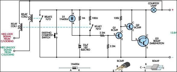
This circuit functions as a courtesy light extender for automobiles, providing illumination for a duration of 15 to 20 seconds. It is triggered by the conventional method of opening a car door, while also sampling the... This circuit is designed...
Using SimPLL's new PLL Wizard, a new Phase-Locked Loop (PLL) can be designed with just a few clicks. A PLL has been designed that tunes from 150 MHz to 170 MHz in 25 kHz steps, utilizing the LMX2306 PLL...