
Courtesy Light Extender
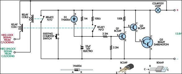
This circuit is designed to enhance the convenience and safety of vehicle entry and exit by extending the duration of interior lighting. The core functionality revolves around a timing mechanism that is activated when a car door is opened. Upon activation, the circuit initiates a light-emitting diode (LED) or incandescent bulb that remains illuminated for a preset interval, typically ranging from 15 to 20 seconds.
The circuit utilizes a microcontroller or a simple timer IC, such as the NE555, to achieve the desired timing function. The door switch, which is normally closed, opens when the door is unlatched, sending a signal to the timer circuit. The timer then begins its countdown, during which it powers the courtesy light.
Additionally, the circuit may incorporate a sampling feature that monitors the ambient light conditions. This feature ensures that the courtesy light only activates in low-light situations, thereby conserving battery life during daylight hours. A light-dependent resistor (LDR) can be employed to detect the ambient light level, providing feedback to the microcontroller or timer IC.
To ensure user safety and prevent the battery from draining, the circuit may include a relay or a MOSFET to handle the load of the courtesy light, allowing it to switch on and off without directly passing through the timer circuit. Furthermore, a capacitor may be included to provide a brief delay in the light extinguishing process, allowing for a smoother transition.
In summary, this courtesy light extender circuit combines a timing mechanism with ambient light sensing to provide a practical solution for enhanced vehicle illumination, ensuring that the interior of the car remains well-lit for a sufficient period after the door is opened.In essence, this circuit is a 15 to 20-second courtesy light extender for cars. It is activated in the usual way by opening a door but it also samples the.. 🔗 External reference
Related Circuits
This circuit is a real core of the dimmer system. This circuit generates a ramp 100 Hz signal which is synchronized to the incoming mains voltage. The ramp signal which is generated will start from 10V and go linearly...
White LEDs have a rated current at a voltage drop of about 3.3 to 3.4 V. It is ideal to be powered from the battery voltage which is slightly larger. Then there is the best energy used. In this...
This is an 8-bit up/down counter that, together with the "8-bit binary to 256 decimal (1 of 256) decoder," forms a run light. The circuit utilizes an 8-bit up/down counter, which is capable of counting both upwards and downwards...
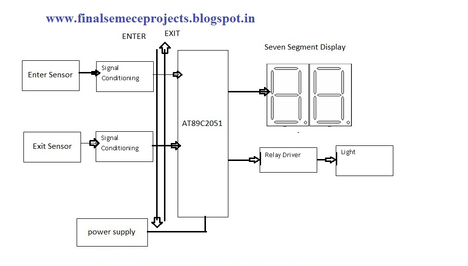
This project involves an automatic room light controller with a bidirectional visitor counter using a microcontroller. It is designed to manage room lighting and accurately count the number of individuals present. When a person enters the room, the counter...
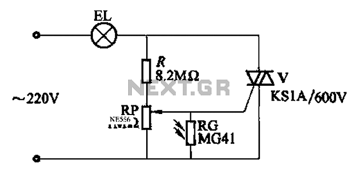
An automatic light control circuit is designed to illuminate a lamp when it is dark and to turn off the light at daybreak. The circuit, as shown in Figure 2-86, employs bidirectional thyristor tubes and features a straightforward design....
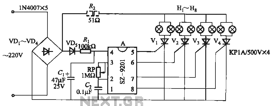
It utilizes the mains supply through a basic DC rectifier circuit. The circuit operates by converting alternating current (AC) from the mains supply into direct current (DC) using a rectifier. A typical implementation involves a bridge rectifier configuration, which consists...