
Analogue VU meter

R1 = 1 M ½
R2 = 820 Ω
R3 = 2.2 kΩ
P1, P2 = 100 kΩ
C1 = 330 nF
C2 = 22 µF
C3 = 1 µF
C4 = 470 µF
T1, T2 = BC 547B
M1 = 1 mA meter
This circuit is designed to drive analog moving coil meters, specifically for use as a VU (Volume Unit) meter. The circuit is connected directly to the line terminals of an audio amplifier, allowing it to monitor the audio signal level. The operation of the VU meter is facilitated by two transistors, T1 and T2, which amplify the incoming audio signal. The amplified signals are then rectified using two diodes, converting the AC audio signal into a DC voltage suitable for the analog meter.
Capacitors C3 and C4 play a crucial role in the circuit by smoothing out the rectified voltage. C3, a 1 µF capacitor, works in conjunction with the meter's response time, ensuring that the meter does not react too quickly to transient peaks in the audio signal. C4, a larger 470 µF capacitor, further stabilizes the voltage, providing a more averaged reading on the meter.
Calibration of the circuit is essential for accurate performance. After assembling the circuit, it must be connected to a tone generator that outputs a 0.3 V signal at a frequency of 1000 Hz. The potentiometer P1 is initially set to its maximum resistance, allowing for full signal input. Potentiometer P2 is then adjusted to ensure that the meter reaches full deflection, indicating the maximum signal level. Following this, P1 is fine-tuned so that the meter reads 0.5 mA, representing half of the meter's full scale.
For stereo applications, this circuit should be duplicated to accommodate two channels, allowing for simultaneous monitoring of both left and right audio signals. The components used in the circuit, including resistors, capacitors, and transistors, are selected to ensure reliable operation and accurate signal representation on the VU meter.This circuit can drive analog moving coil meters, for use as a VU meter. The circuit is left connected to the line terminals of the amplifier. The VU meter works pretty simple. T1 and T2 signal increase. The signal is then rectified by two diodes and fed to the meter. The capacitors C3 and C4 ensure that the voltage is slightly flattened and the meter responds less quickly. After building the circuit must be calibrated. End, the VU meter connected to a tone generator that delivers 0.3 V at 1000 Hz. Then P1 is fully opened, ie the bishop of P1 located at the entrance. Then P2 regulates off so that the full deflection meter. P1 is then adjusted so that meter 0.5 mA (= half results) indicates. For a stereo VU meter circuit should be built twice. Parts List R1 = 1 M ½ R2 = 820 ? R3 = 2.2 kOhm P1, P2 = 100 kOhm C1 = 330 nF C2 = 22 uF C3 = 1 uF C4 = 470 uF T1, T2 = BC 547B M1 = 1 mA meter 🔗 External reference
Related Circuits
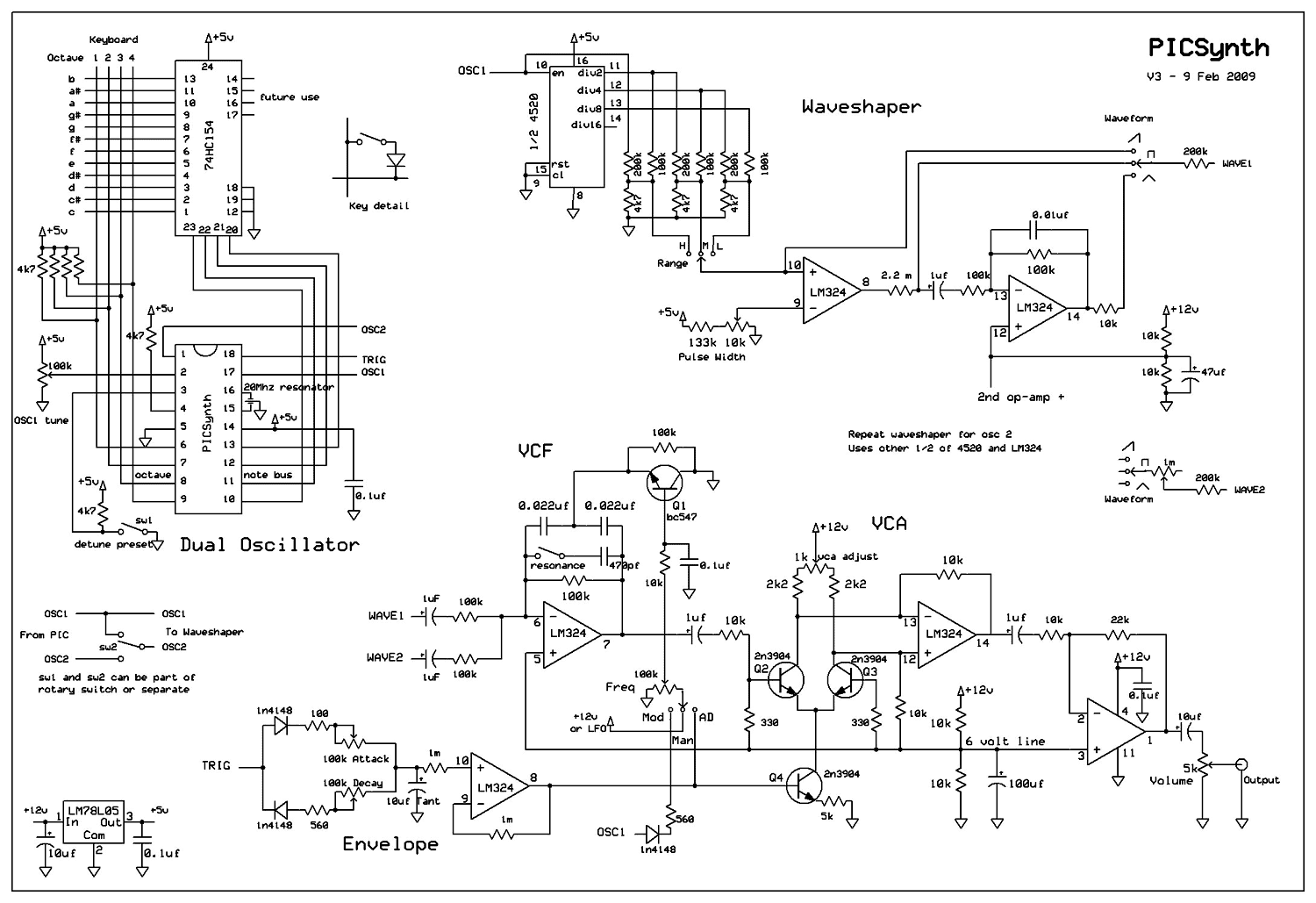
A real analog synthesizer to build using easy to get components, capable of a wide range of sounds. The two oscillators can be detuned for that classic synth sound. Dual oscillator mono synth. Really easy to build using just...
The device employs a microammeter with a full-scale deflection of 50 µA and a resistance of 2 kilohms. The upper limit of the voltmeter's measuring range is 1 V, and within the range of 0.2 to 1 V, the...
The module provides a pre-wired multiplex of a 4-digit common anode LED, which is quite useful. The soldering pad for these signals is shown in the first picture below. A friend provided an AT90S2313 chip, along with a simple...
The rectifier bridge voltage is determined by the U2 element; refer to its datasheet for the maximum voltage specifications. The minimum voltage at this pin should not fall below approximately 9V, or 6.5V if low-dropout type U2 and U3...
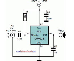
The National Semiconductor LMV225 is a linear RF power meter integrated circuit (IC) in a surface-mount device (SMD) package. It operates over a frequency range of 450 MHz to 2000 MHz. The LMV225 is designed for precise measurement of radio...
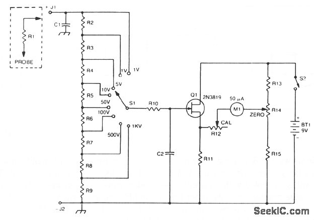
The 2N3819 FET serves as a solid-state voltage output meter (VOM). In this configuration, the 2N3819 functions as a cathode follower. The bias offset, or meter null, is achieved using resistors R14 and R12, while the full-scale calibration is...