
Mic Amplifier

The microphone amplifier circuit is designed to amplify audio signals from various types of microphones, ensuring clear and robust output suitable for further processing or amplification. The schematic typically includes essential components such as operational amplifiers (op-amps), resistors, capacitors, and sometimes transistors, depending on the desired gain and frequency response characteristics.
In this particular design, the op-amp serves as the core amplification element. The choice of op-amp is crucial; it should have low noise and high input impedance to avoid loading the microphone. The circuit may employ a single-supply or dual-supply configuration, depending on the op-amp specifications and the intended application.
Resistors are used to set the gain of the amplifier. The gain can be adjusted by changing the feedback resistor values, allowing for flexibility in amplification levels. Capacitors are typically included in the circuit to filter out unwanted frequencies and to stabilize the power supply, ensuring that the output signal remains clean and free from distortion.
The circuit also includes a power supply section, which may consist of a voltage regulator to provide a stable voltage to the op-amp. Proper decoupling capacitors should be placed near the power pins of the op-amp to minimize noise from the power supply.
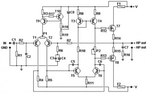
Overall, this microphone amplifier schematic is versatile, capable of handling different microphone types, and is designed for immediate functionality upon assembly, making it an excellent choice for various audio applications.Mic Amplifier schematic diagram. This circuit has been tried on three microphones, one from SONY, and then two Chinese, everything works! With the correct assembly of the device starts to work immediately, and does not need tuning. 🔗 External reference
Related Circuits
The TDA2005 integrated circuit (IC) features a high output power of 10W per channel (stereo) at a load of 2 ohms with a distortion of 10%, and 20W in bridge mode at a load of 4 ohms with a...
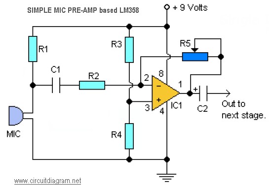
This is a simple audio microphone preamplifier circuit based on a single LM358 IC. The circuit is straightforward, cost-effective, and easy to construct. The component parts list includes: R1, R3, R4 = 10K; R2 = 1K; R5 = 100K-1M...
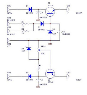
DC fan control circuit for a power amplifier. It features a variable speed DC fan that operates based on the input signal. The speed of the fan's rotation is dependent on the amplitude of the input signal received from...
Both halves of the circuit are identical. Both inputs have a dc path to ground via the input 47k control which should be a dual log type potentiometer. The balance control is a single 47k linear potentiometer, which at...
This basic MOSFET amplifier is simple to construct and low-cost, making it ideal for Hi-Fi amplifiers and instrument amplifiers such as guitars and keyboards. It delivers an output power of ±100 W RMS at an 8-ohm load or ±160...
The TDA2822 is a low-power stereo operational amplifier commonly utilized in Walkman devices and headphones. It is capable of delivering an output power of 250 milliwatts. This operational amplifier is particularly suitable for low-volume production applications and serves as...