
Power audio amplifier schematics with Tda2005

The TDA2005 IC is a versatile amplifier solution suitable for various audio applications, particularly in automotive and consumer electronics. Its ability to deliver significant output power makes it ideal for driving speakers in compact systems. The integrated protection features ensure that the amplifier can withstand various adverse conditions, enhancing its durability and reliability in real-world applications.
In bridge mode, the TDA2005M variant can achieve higher power output, making it suitable for applications where space is limited but power requirements are high. The stereo mode (TDA2005S) allows for a more traditional setup, providing a balanced audio output for two-channel systems. The programmable gain feature enables customization for different audio sources and environments, allowing for optimal performance based on user needs.
The simplicity of the external component requirements minimizes design complexity and assembly time, making the TDA2005 an attractive choice for engineers and hobbyists alike. Its straightforward mounting process facilitates integration into various designs without the need for complex thermal management solutions, as the lack of electrical isolation simplifies the heatsinking process. This characteristic is particularly beneficial in compact designs where space and weight are critical considerations.
Overall, the TDA2005 IC represents a robust and efficient solution for audio amplification, combining high performance with ease of use and integration. Its design reflects a thoughtful approach to both functionality and reliability, making it a valuable component in modern audio systems.The Tda2005 IC has a high output power: PO=10W+10W @ RL=2ohm, d=10% (stereo) and PO=20W @ RL=4ohm, d=1% (bridge) for Vs=14. 4V. The high reliability of the IC comes from the various protections against: output DC and AC short circuit to ground, overrating chip temperature, load dump voltage surge, fortuitous open ground and very inductive loads.
Th e IC can be used used in bridge (TDA2005M) or stereo (TDA2005S) amplifiers - with or without boostrap - with easily programmable gain and bandwidth. The Tda2005 needs a very low number of external components, and has a very simple mounting system with no electrical isolation between the package and heatsink.
🔗 External reference
Related Circuits
The preamplifier described is engineered with a low output impedance, specifically designed to handle long cable runs. This feature allows for listening to a remote music source without the need for expensive screened cables. The preamplifier boasts a very low...
.jpg)
The HID ballast circuit consists of a buck stage for regulating lamp current and power, a full-bridge output stage that generates a low-frequency (200Hz) AC square-wave voltage and current to drive the lamp, and an ignition circuit that produces...
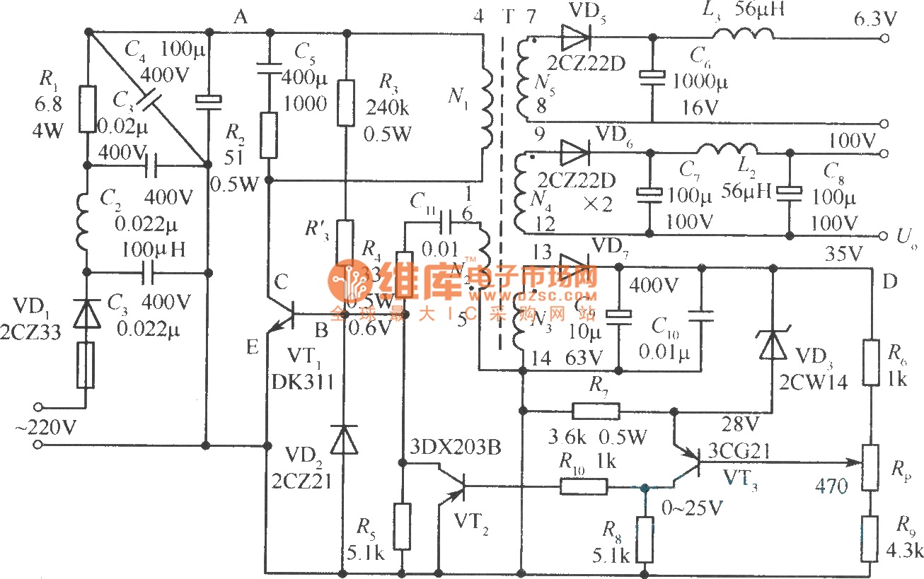
The diagram illustrates the output sampling winding of an isolated switching power supply. In the diagram, T represents a high-frequency transformer; N2 denotes the self-oscillation positive feedback winding; N3 is the error amplifier; VTS is the winding that provides...
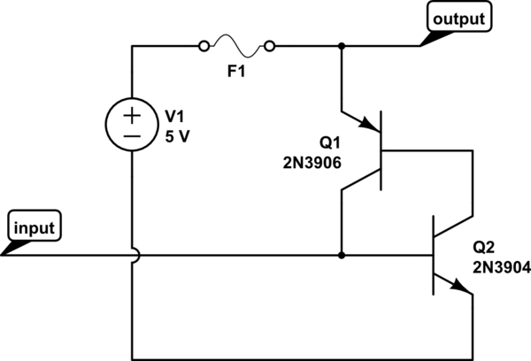
The circuit should default to the "on" state when first connected. However, if a specific signal goes high for a brief duration (approximately 10 microseconds), the circuit should turn off and remain off. The challenge lies in achieving the...

The TPS61200 specifications indicate that GND serves as the control/logic ground, while PGND is designated as the power ground. However, this distinction is not accurately represented in the symbols used in the diagram. There is also confusion regarding the...
This page contains some information on circuits which can be used for triggering stroboscopes from external circuits. The circuits here are designed to be integrated into stroboscope circuits so that they can be triggered using an external trigger pulse....