
Micro Function Generator
The described function generator is an advanced electronic device that utilizes a combination of integrated circuits and microcontroller technology to provide precise waveform generation for various applications. The use of Direct Digital Synthesis allows for high-resolution control over output frequencies and waveforms, making it suitable for testing and experimentation in both educational and professional environments. The compact design and battery operation facilitate portability, enabling users to deploy the generator in various settings without being constrained by power sources.
The microcontroller at the heart of the system plays a crucial role in managing the synthesis process, ensuring that waveform generation remains stable and accurate. The implementation of a phase accumulator enhances the precision of the output by allowing for fine-tuning of frequency adjustments, which is essential for applications requiring specific frequency characteristics. The R-2R ladder network for digital-to-analog conversion is a cost-effective solution that delivers satisfactory performance for generating analog signals from digital values.
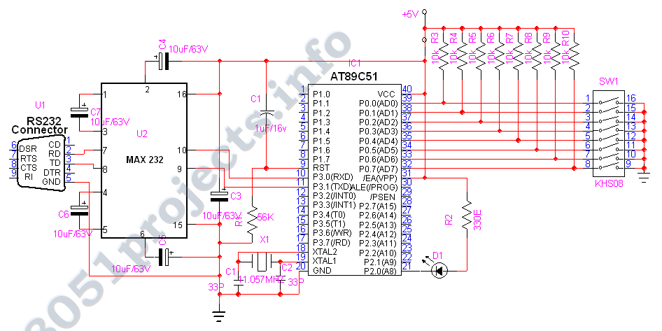
Furthermore, the communication interface via RS232 allows for easy integration with computers, enabling users to control the generator remotely and automate testing processes. The half-duplex communication ensures efficient data transfer while minimizing conflicts in signal transmission. The careful design considerations, including reverse voltage protection and the ability to handle various power supply levels, contribute to the reliability and robustness of the device.
Overall, this function generator represents a significant advancement in electronic waveform generation, combining affordability with high performance, making it an invaluable tool for engineers, educators, and hobbyists alike.There are two main types: the most common is the Wein Bridge oscillator variety, which has low distortion, but offers only sinewave output and can suffer from amplitude bounce as you change frequency. The type which offers greater versatility of waveform and frequency range, the usual function generator type, typically lack stability and accuracy.
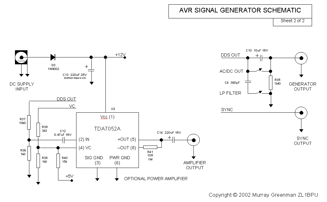
This unit meets all these requirements, and is small - fits in the palm of your hand - and is battery operated. It also has no "front panel" - you control it from a PC or computer terminal. The generators are quite inexpensive to build - just two or three ICs and a couple of transistors. One of the ICs is an AVR RISC microcontroller - inexpensive, and quite powerful. It operates in an unusual manner, using a Direct Digital Synthesis (DDS) technique developed by Jesper Hansen to create very accurate signals. Some of the features of the Function Generator are: Many of the parameters, such as frequency range, step size and frequency response can be tailored to suit other applications.
The picture below, of the simple PC control panel for the generator, shows a 4MHz version in use, with an upper limit of about 133 kHz. The absolute upper frequency limit of any generator using this microcontroller technique is set by the maximum clock frequency (currently 16 MHz).
The upper limit of the generator is thus about 500 kHz. There is no lower limit. A 12. 8MHz version for use as an Exciter for the Amateur LF bands is also available. Power for the unit comes from a tiny 5V regulator, which runs from a DC supply (battery or AC adaptor) with an output of between 6V and 15V. The supply is reverse voltage protected. The RS232 communications with the PC uses simple transistor level shifters. The transmit signal from the microcontroller requires a negative voltage supply, and for simplicity, this voltage is derived from the mostly idle PC transmit data line, which is normally negative.
Communications is half - duplex, using a 19200 bps data rate (19200-N-8-1). Except at start-up, the generator only replies when spoken to. The microcontroller, an Atmel AT90S2313-10PC, has a very simple main program consisting of a very tight and very fast sampling process, taking data from one of four tables at a fixed rate, to place the data on an output port. The Direct Digital Synthesis technique works not as you would expect, by stepping sequentially through a table of waveform values at a variable rate, but instead uses a fixed very high frequency (about 1 MHz) sampling rate, and a user controlled step size to address the table.
The counter used to control the table address is called the phase accumulator, and this accumulator and the user controlled step value are both very large (24 bit) numbers. The most significant eight bits of the accumulator select the correct table value at each sample point.
The eight bit digital values at the port are converted to an analog waveform by a simple R-2R resistive ladder. The required waveform is reconstructed by an anti-aliasing interpolative filter at the output (otherwise known as a low pass filter!) While the synthesizer is running, nothing is allowed to interrupt the process, as interruptions would slow down or distort the waveform.
Commands to change the operating parameters are received from the serial communications link, which operates via an interrupt and stops the generator while the command is processed. The interruption can be as short as 2 µs (in sweep mode), or as long as several milliseconds, depending on the command sent.
At audio frequencies the glitch in the generated waveform caused by the shorter commands is hardly noticeable. Commands are provided to change the frequency, offset the frequency (by microscopic amounts), ch 🔗 External reference
Related Circuits
The 8051 microcontroller features a transmit channel and a receive channel for serial communication. The transmit data pin (TXD) is designated as P3.1, while the receive data pin (RXD) is located at P3.0. The serial signals on these pins...
The sound card for a PC typically includes a microphone input, speaker output, and occasionally line inputs and outputs. The microphone input is specifically designed for dynamic microphones with an impedance range of 200 to 600 ohms. An adaptation...
This window generator utilizes a single LM324 operational amplifier and includes two adjustable set points. When the two comparators formed by U1B go high, LED1 illuminates. When U1C goes high, the LED turns off. Hysteresis is implemented using 10...
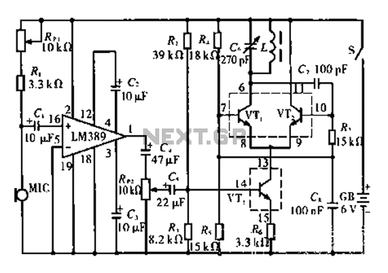
This circuit is tested and functional. The LM389 integrated circuit serves as the core element, where the voice channel number is acquired by the microphone (MIC) and converted into electrical signals. These signals are amplified by the volume control...
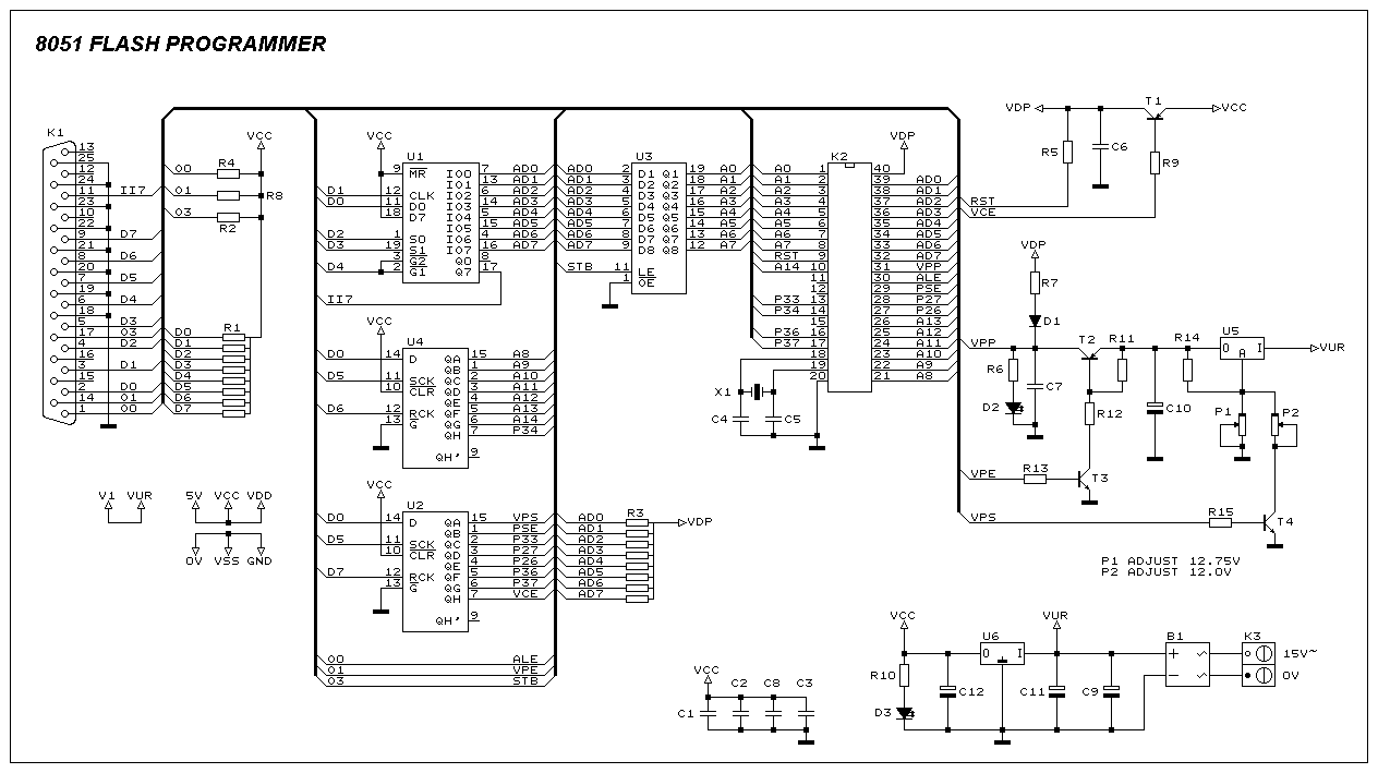
This programmer was designed to be flexible, economical, and easy to build. The programmer hardware utilizes standard TTL series parts, and no special components are used. The programmer is interfaced with the PC parallel port, and there are no...
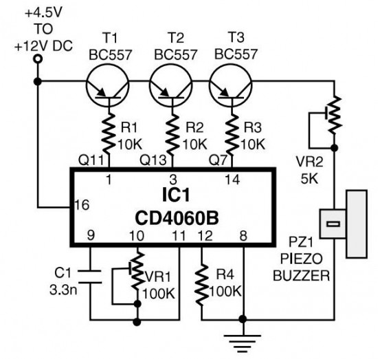
The circuit generates pulses of 1.25 Hz from pin 1 and 20 Hz from pin 14. The three output pins of IC1 are connected to the base terminals of transistors T1, T2, and T3 through resistors R1, R2, and...