
microphone computer circuit schematic
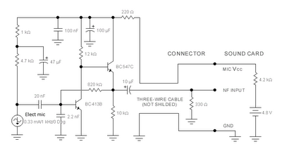
The described circuit for adapting an electret microphone to a PC sound card employs a two-stage amplifier configuration that enhances the microphone's output signal while maintaining signal integrity over distance. The first stage utilizes the BC413B transistor in a common emitter arrangement. This configuration is advantageous as it provides voltage gain, which is critical for boosting the low-level signal generated by the electret microphone. The choice of the BC413B is appropriate due to its suitable frequency response and gain characteristics, making it ideal for audio applications.
Following the initial amplification stage, the second stage employs a BC547C transistor configured as an emitter follower. This stage serves several purposes: it provides a high input impedance, which is beneficial for interfacing with the microphone, and a low output impedance, which is crucial for driving the cable to the sound card. The emitter follower configuration allows the circuit to buffer the amplified signal, ensuring that it can drive longer cable lengths without significant signal degradation or loss.
The overall design incorporates a power supply, typically a battery, which powers the electret microphone and the transistor stages. Careful consideration of the power supply voltage and current ratings is necessary to ensure the proper operation of the transistors and the microphone. Additionally, the use of a screened cable is essential to minimize electromagnetic interference (EMI) and radio frequency interference (RFI), which can introduce noise into the audio signal.
In summary, this circuit design effectively adapts an electret microphone for use with a PC sound card by employing a composite amplifier configuration that enhances signal quality and maintains integrity over distance, ensuring a reliable and clear audio input for various applications.The sound card for a PC generally has a microphone input, speaker output and sometimes line inputs and outputs. The mic input is designed for dynamic microphones only in impedance range of 200 to 600 ohms. Lazar has adapted the sound card to use a common electret microphone using this circuit. He has made a composite amplifier using two transistor s. Transistor BC413B operates in common emitter to give a slight boost to the mic signal. This is followed by an emitter follower stage using transistor BC547C. This is necessary as the mic and circuit and battery will be some distance from the sound card, the low output impedance of the circuit and screened cable ensuring a clean signal with minimum noise pickup. 🔗 External reference
Related Circuits
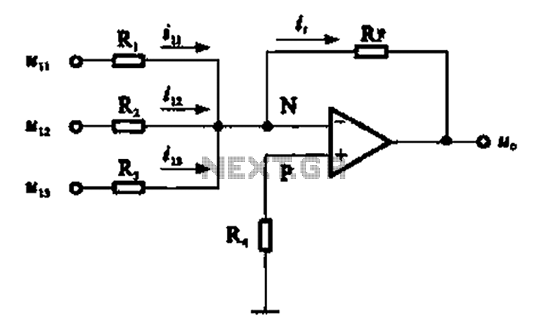
An adder circuit, specifically the inverting adder circuit, utilizes the inverting input of an operational amplifier to process signals. Voltage inputs are added through resistors connected to the inverting input terminal of the operational amplifier. The circuit configuration, as...
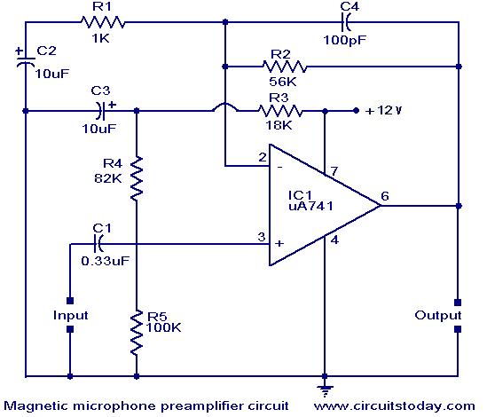
A preamplifier for magnetic pickups of record players is presented. The uA 741 is utilized as an AC-coupled non-inverting amplifier operating on a single supply. The amplifier gain is determined by the feedback components, where C2 manages the low-frequency...
This circuit below shows a teleremote circuit that enables the switching on and off of appliances through telephone lines. The teleremote circuit utilizes a telephone line as a medium for controlling electrical appliances from a distance. The primary components...
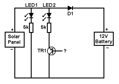
A small solar panel is used to maintain a 12V car battery. The panel provides approximately 75mA of current to the battery under full sunlight conditions. The described circuit employs a solar panel specifically designed for battery maintenance applications. The...
This circuit is designed to provide alerts after a predetermined time interval. It is ideal for tabletop games that necessitate a fixed duration for answering questions or moving pieces. In this context, it serves as a contemporary alternative to...
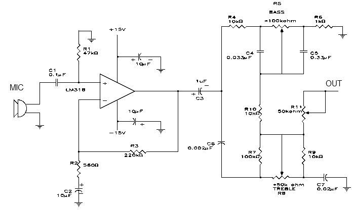
This simple microphone preamplifier is based on the LM318 operational amplifier. The LM318 operates as a standard non-inverting amplifier. Resistor R1 provides a ground input path for the bias current of the non-inverting input. The combination of R2 and...