
741 Microphone amplifier

The described preamplifier circuit utilizes an LM741 operational amplifier (op-amp) as the main amplification component. The circuit is designed to amplify the low-level audio signals from a microphone to a higher line level suitable for further processing or amplification.
The input from the microphone is connected to the non-inverting input of the op-amp. A biasing network may be implemented to ensure that the microphone receives the appropriate power supply, which is typically half of the supply voltage to maintain the op-amp's operational range. This configuration allows the op-amp to effectively amplify both the positive and negative swings of the audio signal.
The gain of the amplifier can be adjusted using a potentiometer (P1), which is connected in the feedback loop. This potentiometer allows for a variable gain setting from 10 to 101 times, providing flexibility in the amplification level based on the specific application requirements.
The component values in the parts list indicate a variety of resistors and capacitors used to set the gain and frequency response of the circuit. Resistors R1 and R2, each valued at 2.2 kOhm, are likely part of the feedback network, while R3 (220 kOhm) and R4 (220 Ohm) may serve to set the input impedance and gain characteristics.
Capacitors C1 through C7 are used for coupling, decoupling, and frequency stabilization. For instance, C1 (1 µF) and C2 (22 µF) may be used for AC coupling to block DC offsets from the microphone signal, while C6 (100 pF) could be employed for high-frequency stabilization to prevent oscillations. The values of C3, C4, and C5 (100 µF and 10 µF) suggest that they are used for power supply decoupling, ensuring stable operation of the op-amp under varying load conditions.
Overall, the circuit design provides a robust solution for amplifying microphone signals, making it suitable for various audio applications, including recording and live sound reinforcement. The choice of components and their configuration is fundamental to achieving the desired performance characteristics of the preamplifier.This preamplifier uses a type of IC 741, and can boost a microphone signal to line level. The microphone signal is connected to the "input" put. Any power for the microphone jack of the "food" are met. Here half the supply voltage. Using the gain potentiometer P1 can be adjusted from 10 to 101 times. Parts List R1, R2 = 2.2 kOhm R3 = 220 kOhm R4 = 220 ? R5 = 1 kOhm R6 = 100 kOhm R7 = 470 kOhm P1 = 10 kOhm C1 = 1 V ?F/16 C2 = 22 V ?F/16 C3, C5 = 100 V ?F/16 C4 = 10 V ?F/16 C6 = 100 pF C7 = 4.7 V ?F/16 IC1 = LM 741 🔗 External reference
Related Circuits

In recent years, there has been a growing demand for higher reimbursement structures among music lovers and manufacturers of tube amplifiers. This is attributed to the perception that tube sound is sweeter, richer, and incomparably cleaner. However, tube amplifiers...
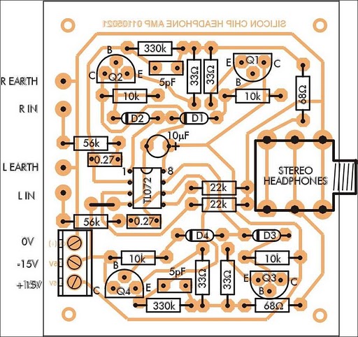
In addition to its primary function as a headphone amplifier, this circuit can be utilized for various applications requiring a wide bandwidth low-power amplifier. It is designed around an operational amplifier (op-amp), with its output current enhanced by a...
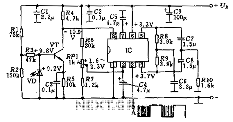
The circuit utilizes an integrated amplifier, resulting in a simple and compact design. The TDA4050 IC is employed, where a weak signal is received by the infrared photodiode (VD) and first passes through a transistor amplifier. The circuit is...
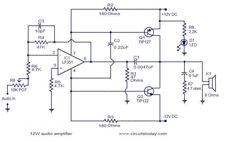
The circuit presented is a simple audio amplifier capable of delivering 12W to an 8 Ohm speaker. The operational amplifier IC TL081 serves as the preamplifier in this design. Alternatively, any operational amplifier with compatible power supply ratings can...
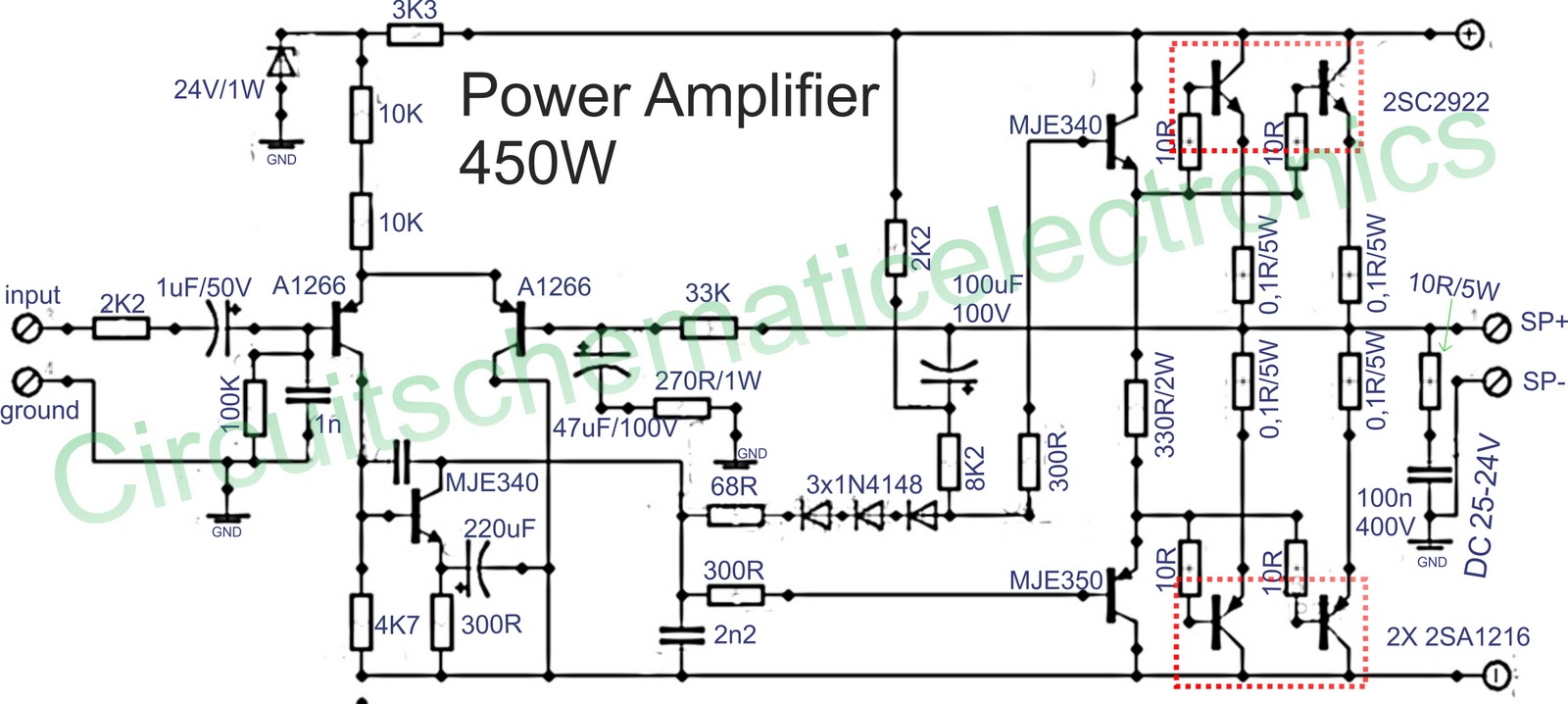
Below is a circuit of power amplifiers with a power output of 450 watts in mono mode. These amplifiers are frequently utilized in high-power applications, suitable for events, and designed for enclosed spaces. This amplifier is appropriate for woofers...
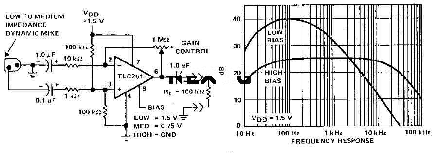
A microphone preamplifier utilizing a CMOS operational amplifier powered by its own battery is compact enough to fit within a small microphone casing. The amplifier functions with a 1.5V battery and exhibits low supply currents. This preamplifier operates at...