
Micro-Ohm Meter Senior Project Page
The digital micro-ohm meter circuit integrates several key components to ensure accurate measurements and reliable performance. The primary component, the 68HC11 microcontroller, serves as the central processing unit, executing the necessary calculations and controlling the overall operation of the device. The microcontroller interfaces with a BJT, which functions as a voltage-controlled switch, enabling precise control of the current flowing through the shunt.
The circuit includes a PI controller that regulates the output current to maintain a constant level, essential for accurate resistance measurements. The A/D converter plays a crucial role in digitizing the voltage readings from the shunt, allowing the microcontroller to process these values effectively. The front panel switch allows the user to set the predetermined voltage across the known resistance, which is critical for the current calculation.
Upon applying current to the shunt, the circuit measures the resulting voltage drop. The microcontroller then computes the resistance using Ohm's law (R = V/I), where V is the measured voltage and I is the constant current. The calculated resistance value is converted into ASCII format, making it suitable for display on the LCD, providing users with a clear and readable output.
This digital micro-ohm meter is designed to be user-friendly and efficient, with a focus on minimizing costs while maintaining high accuracy and reliability. Its application in verifying shunt resistance values in a laboratory setting highlights its importance in ensuring the integrity of electrochemical measurements and diagnostics.A digital micro-ohm meter is necessary to verify the condition of shunts used in the Electrochemical Analysis & Diagnostics Laboratory (EADL) at Argonne National Laboratories. A shunt is basically a small resistor. They are used to measure current. The micro-ohmmeter will push 0. 5A of current through the smaller shunts and 10A through the larger s hunts. When a current is put through a shunt it produces a corresponding voltage. With the current and voltage known the abilities of the 68hc11 would be utilized to calculate the corresponding resistance. The digital micro-ohmmeter is very simple in design. Basically the circuit is a constant current flowing into a resistance value that is known and a resistance value that is unknown.
When the voltage across the resistance value that is known reaches a certain value, the exact current can be calculated. Now that the current is known, the A/D will find voltage across the unknown shunt. These values will be stored into memory and by using the floating point software. The look up table will be found by dividing the voltage by the current. This will find resistance in the unknown shunt. This simple set-up is the basis for our project. The digital micro-ohmmeter utilizes one BJT, a PI controller, and an analog to digital converter to provide the constant current function.
Refer to Figure below for a block diagram. Simply put, the BJT is used as a voltage controlled switch. The predetermined voltage value across the calibrated resistance is determined by the front panel switch, and is stored in the micro controller as the current value. The voltage read off of the shunt to be measured is then divided by the current value obtained to determine the resistance value.
This resistance value is then converted to ASCII in order to be displayed by the LCD. The micro-ohm meter will be used by Argonne National Laboratories to verify resistance values of shunts. This system will be far cheaper than any other system on the market. 🔗 External reference
Related Circuits
This project involves a USB interface for an alphanumeric LCD display, such as the 4x20 model, which can be controlled using the LCD Smartie program. The USB interface is implemented with the PIC18F2550 microcontroller and utilizes USB LCD modules....
This audio noise filter circuit is a bandpass filter designed for the audio frequency range. It effectively filters out unwanted signals that fall outside the audio frequencies. The circuit consists of two filters: a low-pass filter and a high-pass...
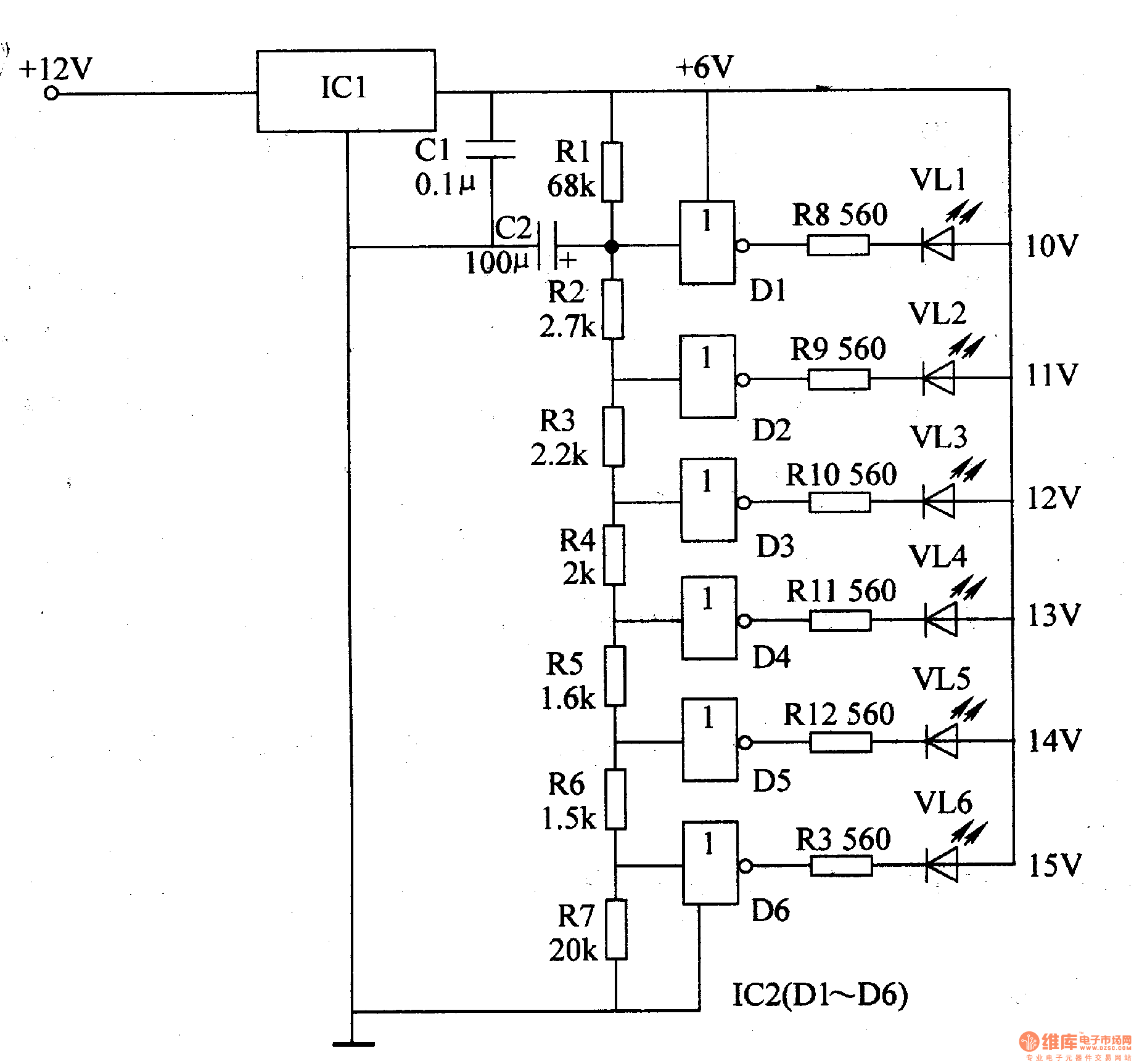
The LED car voltmeter comprises a filter circuit, a voltage distribution filter circuit, a voltage amplifier circuit, and an LED display circuit, as illustrated in Figure 7-77. The regulator filter circuit includes a 3-terminal IC (IC1) and a filter...
This digital DIY tachometer for bicycles utilizes two reed switches to gather speed information. The reed switches are positioned near the wheel rim, where permanent magnets are mounted on the wheel spokes. As the spokes rotate, the magnets pass...
This circuit is a low-cost frequency meter that operates within the range of 1 Hz to 1 MHz. It utilizes an IC1 Schmitt trigger to regulate the input signal, adjusting it to a suitable level for IC2, IC3, and...
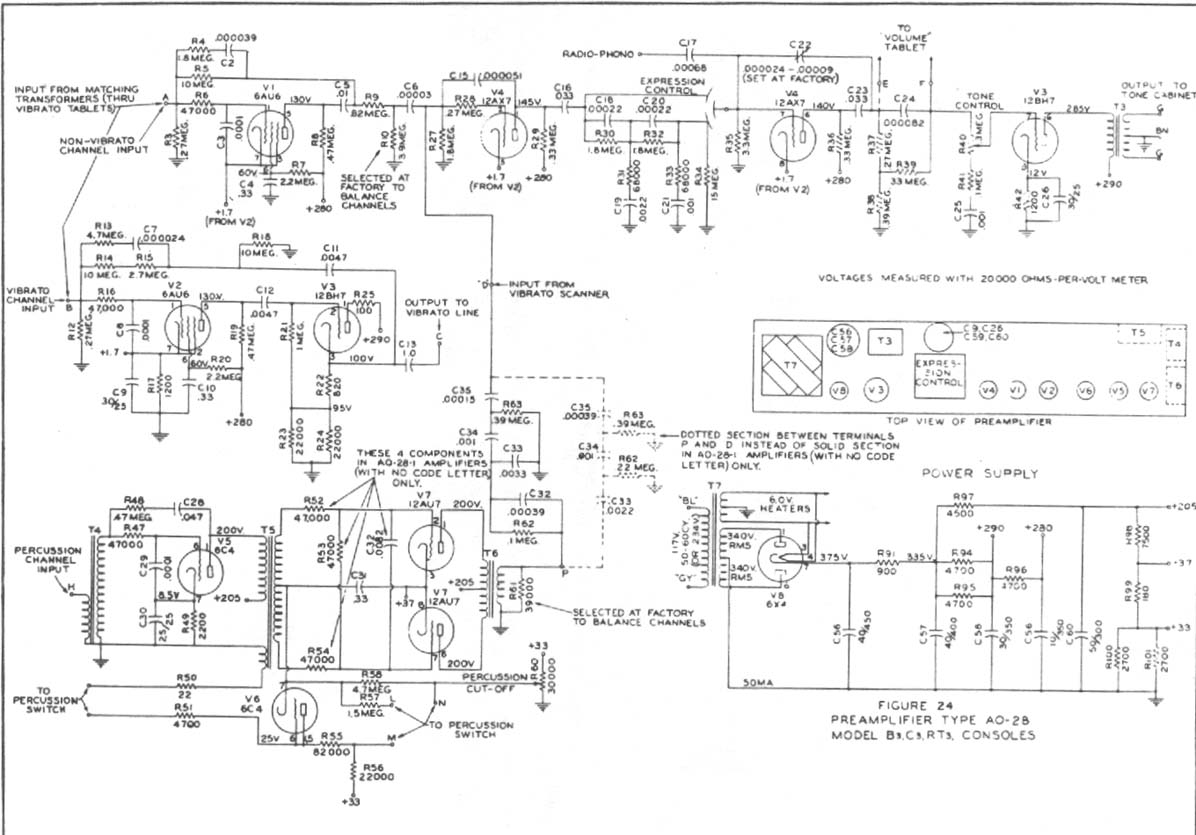
Construct a preamplifier intended to accept a 1/4" keyboard line-level signal and drive a Leslie 147 amplifier. The preamp will utilize a 12AX7 and 12BH7, following the design of a Hammond Organ preamp. The focus will be on the...