
Micro Wireless Monitor FM FM transmitter circuit two
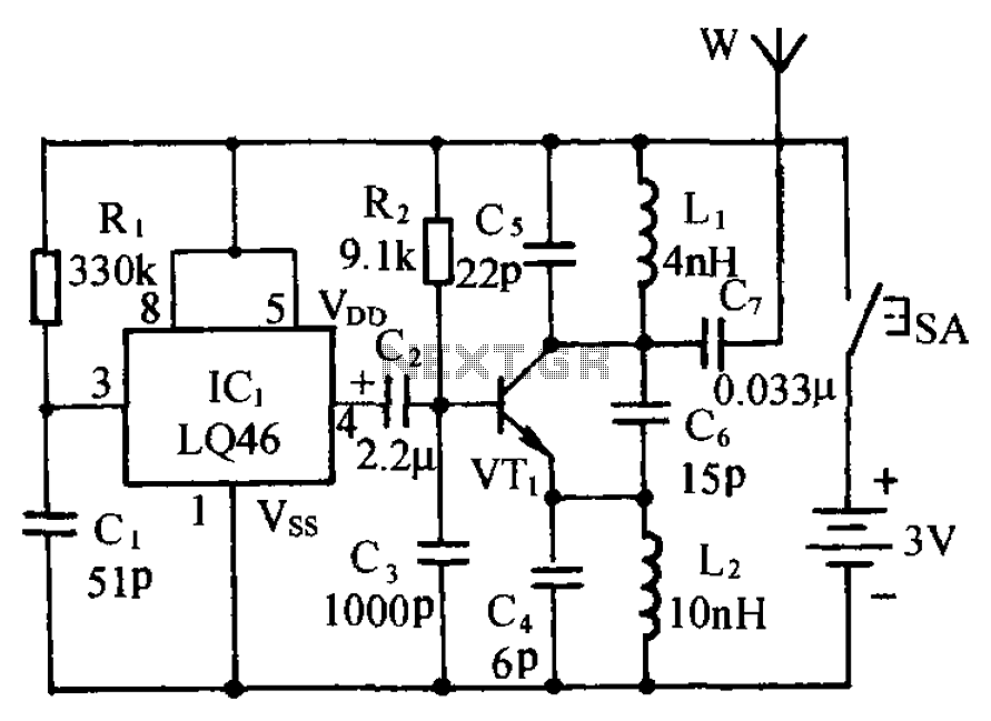
The FM transmitter circuit is designed to modulate audio signals, such as voice or sound, onto a carrier frequency suitable for FM broadcasting. The core components typically include an oscillator, a modulator, and an antenna. The oscillator generates a stable RF frequency, which is then modulated by the audio input. This modulation process alters the frequency of the carrier wave in accordance with the amplitude of the audio signal, creating an FM signal that can be transmitted over the air.
For construction, the circuit often utilizes readily available components, such as transistors, resistors, capacitors, and an inductor to form the oscillator. The choice of components can impact the range and quality of the transmission. The antenna is crucial for effective broadcasting, and its design can vary depending on the desired transmission range.
The circuit layout should be carefully designed to minimize interference and ensure stable operation. Proper grounding and shielding techniques are essential to reduce noise and enhance performance. Additionally, the power supply must be regulated to provide consistent voltage to avoid distortion in the transmitted audio.
This FM transmitter can be used in various applications, such as personal broadcasting, educational purposes, or as a simple communication device. However, it is important to consider local regulations regarding FM transmission to avoid interference with licensed broadcasts. Circuit is shown. It consists of language and sound circuit FM transmitter circuit. Its circuit is simple and easy to manufacture. It is with an ordinary FM (FM) radio compatib le, the scene may occur listen, to take preventive measures.
Related Circuits
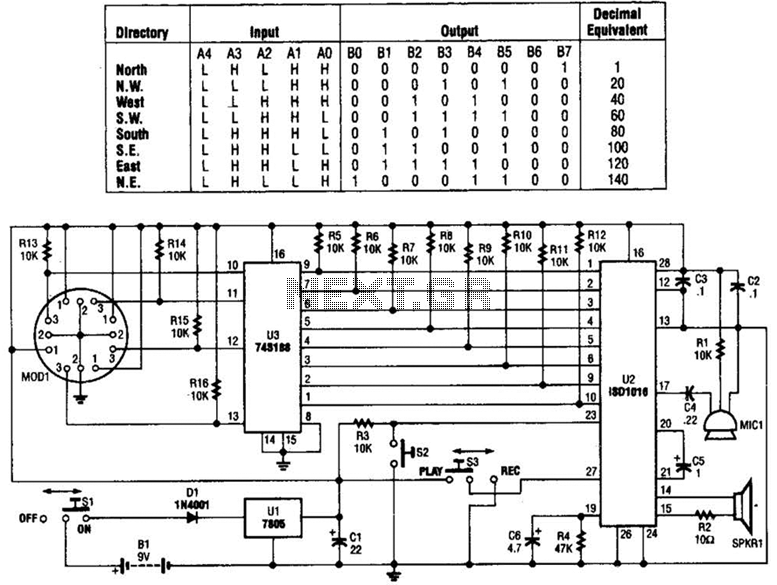
A talking compass consists of a Hall-effect direction sensor (MODI) and an ISD1016 analog audio storage device. It can store eight two-second announcements for each of the eight primary compass directions. The Talking Compass includes a digital compass (MODI),...
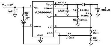
The ADM666A application note provides a detailed explanation of a low-cost battery charger circuit, including maximum output voltage, charge termination voltage calculation, battery voltage level monitoring, and circuit efficiency optimization. The ADM666A utilizes an NPN transistor and a P-channel...
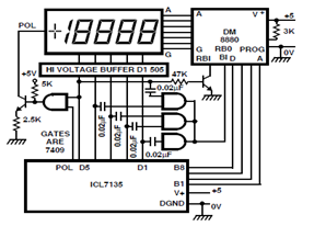
A circuit diagram for driving a plasma-type display using the ICL7135 is presented in the schematic. This application highlights the versatility of this integrated Analog to Digital Converter device. The ICL7135 is a high-precision, low-power, integrating Analog to Digital Converter...
The simple pressure sensor alarm is constructed using a few inexpensive and readily available components. The operation of this circuit is straightforward and self-explanatory. When powered by a 9V compact battery, the active piezo sounder at the output of...

The relay power in the linear circuit is derived from a -120 V bias supply, while the transmit keying output from the Kenwood device is +12 V with a maximum current of 10 mA. A critical component of this...
Here's PLL FM transmitter circuit from china. This circuit uses the familiar 2SC1971 for final power amplifier stage. The PLL controller of the FM transmitter use SAA1057 and PIC16F628 (download HEX file). More: If want to change the active...