
microcontroller complete code midi emulated ps 2 keyboard
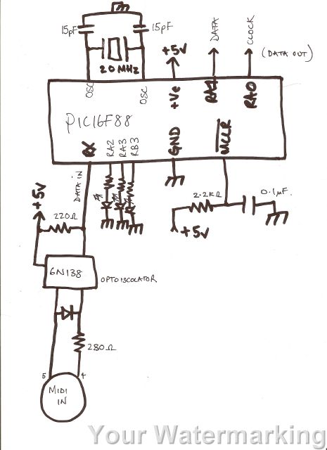
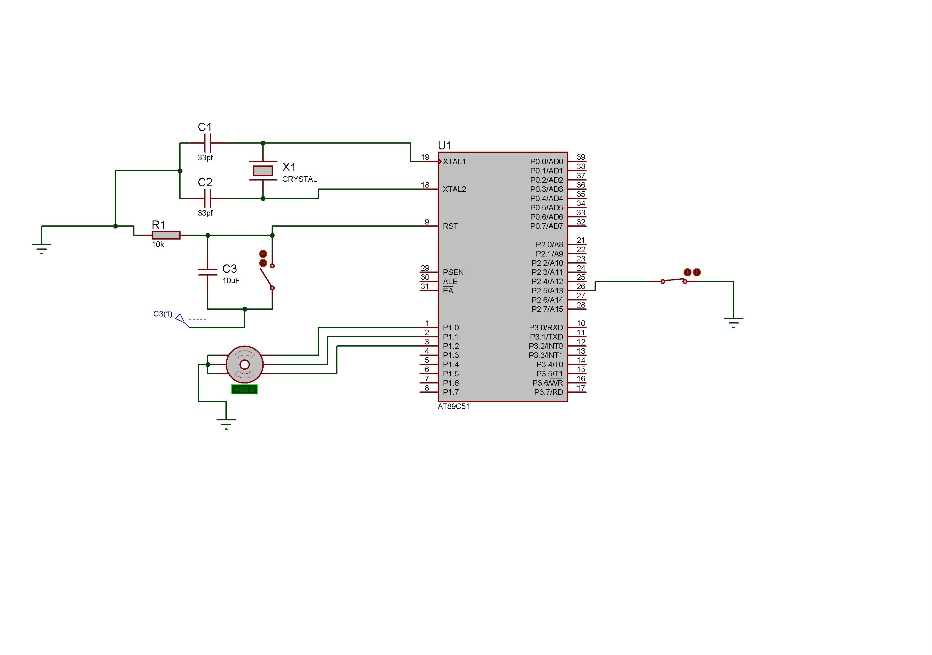
The described circuit is designed to interface with MIDI devices using a USART (Universal Synchronous Asynchronous Receiver Transmitter) for data reception and processing. The primary function of the circuit is to receive MIDI messages, specifically "note on" messages, which are identified by examining the first byte of the incoming data. This byte is masked to isolate the relevant bits, allowing for the determination of whether it corresponds to a MIDI "on" message.
Upon receiving a valid MIDI "on" message, the next byte of data is processed through a lookup table, converting it into a format suitable for transmission. The output is then sent through RA0 and RA1 pins, which emulate the behavior of a PS/2 keyboard, enabling the circuit to communicate with devices that expect keyboard input.
The implementation of diagnostic LEDs serves as a feedback mechanism for troubleshooting the circuit. LED1, which remains constantly on, may indicate an issue with the power supply or configuration settings. LED2's flashing behavior followed by a constant state could suggest intermittent operation or a fault in the code execution. The failure of LED3 to illuminate at all may point to a complete malfunction in that segment of the circuit or an error in the configuration settings.
The configuration settings provided are critical for the operation of the microcontroller within the circuit. These settings include disabling various features such as code protection (_CP_OFF), watchdog timer (_WDT_OFF), and enabling the high-speed oscillator (_HS_OSC), which are essential for ensuring reliable operation and performance of the system. Proper attention to these configurations is necessary to rectify the issues observed with the diagnostic LEDs and to ensure the successful transmission of MIDI data.hi i have been working on this code for a while now and i have come to a complete dead end. the following code takes midi data on the rx pin of the usart, saves the 3 bytes of data in the cblock, tests the first byte to see if it is a midi on message (xxxx1001) by masking the upper nibble and subtracting from a constant to see if it equals zero, i f so take the next byte, convert it using the lookup table. THEN send this data via ra0 and ra1 in a loop which emulates a ps/2 keyboard after calculating the odd parity bit. first things first, i wrote the diagnostic LED part which doesn`t work, led 1 is constantly ON and led2 flashes on, then off, then is constantly on, AND THEN led 3 won`t even come on.
_CONFIG _CONFIG1, _CP_OFF & _CCP1_RB0 & _DEBUG_OFF & _WRT_PROTECT_OFF & _CPD_OFF & _LVP_OFF & _BODEN_OFF & _MCLR_ON & _PWRTE_ON & _WDT_OFF & _HS_OSC 🔗 External reference
Related Circuits
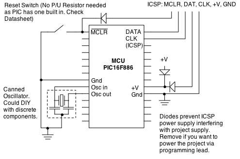
Microcontrollers (MCUs) are versatile integrated circuits (ICs) that enhance the functionality of electronics, robotics, and various other projects. Microcontrollers serve as the brain of embedded systems, providing control, processing, and communication capabilities in a compact form factor. They typically consist...
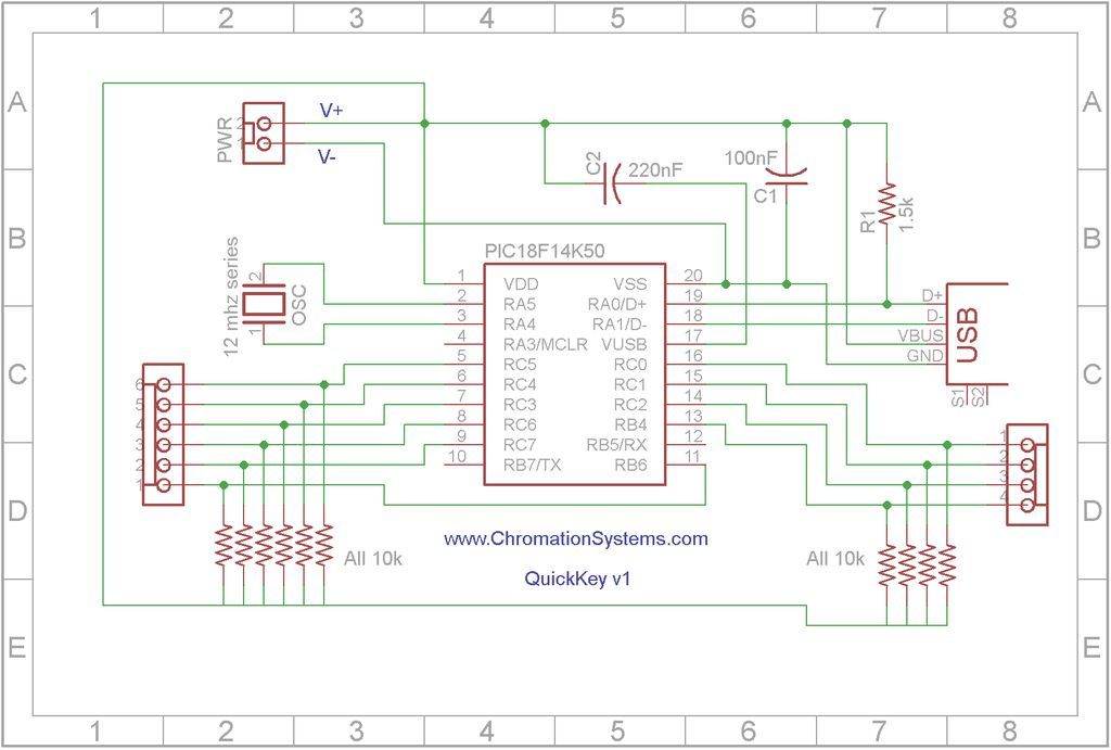
Quick Key Adapter, 10 Button HID Keyboard. This document outlines the process of creating a USB-connected Human Interface Device (HID) keyboard featuring 10 button inputs. The Quick Key Adapter is designed to facilitate user interaction through a compact keyboard interface....

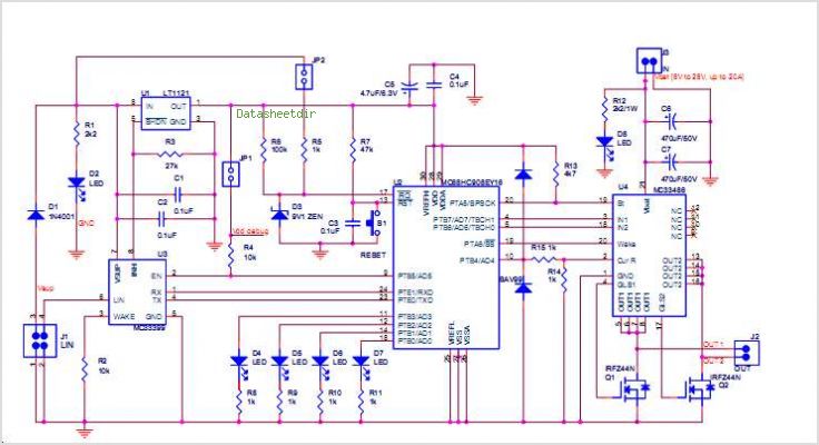
The board can now be tested. Set the DIP switch to Switch1 ON, Switch2 OFF (15-second delay), Switch3 ON, and Switch4 OFF (4 rings to activate half for switching ON). To switch ON relay 1 (connected to RB0 of...
The WS2512-TR1G is a Wide-band Code Division Multiple Access (WCDMA) Power Amplifier (PA) designed as a fully matched 10-pin surface mount module, specifically developed for WCDMA handset applications. This power amplifier module operates within a frequency range of 1920-1980...
Stepper motors consist of a permanent magnet rotating shaft, known as the rotor, and electromagnets on the stationary part that surrounds the motor, referred to as the stator. One complete rotation of a stepper motor is illustrated. At position...
This simple CPO is for those who want to practice Morse Code in a different way, ie without the morse key. It can be also used as a touch operated door bell. The popular timer IC555 is wired as...
Warning: include(partials/cookie-banner.php): Failed to open stream: Permission denied in /var/www/html/nextgr/view-circuit.php on line 713
Warning: include(): Failed opening 'partials/cookie-banner.php' for inclusion (include_path='.:/usr/share/php') in /var/www/html/nextgr/view-circuit.php on line 713