
Telephone operated remote control using PIC16F84A microcontroller

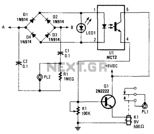
The circuit described involves a control board utilizing a DIP switch configuration to manage the operation of a relay. The specific settings for the DIP switches are critical for proper functionality. Setting Switch1 to ON and Switch2 to OFF initiates a 15-second delay, while Switch3 being ON and Switch4 being OFF prepares the system to respond to a specific sequence of activation signals, indicated by 4 rings. This sequence is essential for activating relay 1, which is connected to the RB0 pin of the main circuit.
To ensure that the relay operates as intended, it is imperative to follow the setup instructions carefully. The relay is likely designed to control a higher power load, and the RB0 pin serves as a digital output signal that triggers the relay's activation. The reliability of the circuit is contingent upon precise construction, including correct component placement, soldering, and adherence to the specified configuration of the DIP switches.
In practical applications, the user should verify the integrity of the circuit after assembly, checking for any potential short circuits or misconfigured components that could lead to malfunction. The circuit's operation can be further validated through a multimeter or oscilloscope to monitor the output signals at RB0 during the activation process.
It is also important to note that the circuit's design is intended for personal use, and any commercial application or reproduction of the schematic requires explicit permission from the authors. The information provided is intended for educational purposes, and users should exercise caution and perform due diligence when implementing the circuit in their projects.You can test the board now. For example set the DIP switch to Switch1 ON, Switch2 OFF (15 sec delay) & switch3 ON, switch4 OFF (4 rings to activate half for switching ON). If you want to switch ON relay 1 (connected to RB0 of main circuit) then you have to do the following: IMPORTANT: This circuit has been tested by me and found to work correct
ly. I cannot guarantee that the circuit will work at your end since it depends on error free construction and usage. Please do not contact for any support and requests, any such requests will not be entertained. Disclaimer: All the information present on this site are for personal use only. No commercial use is permitted without the prior permission from authors of this website. All content on this site is provided as is and without any guarantee on any kind, implied or otherwise.
We cannot be held responsible for any errors, omissions, or damages arising out of use of information available on this web site. The content in this site may contain COPYRIGHTED information and should not be reproduced in any way without prior permission from the authors.
🔗 External reference
Related Circuits
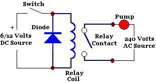
A relay is an isolated switch, with no direct connection between the switching device and the load. Relays are commonly used to control high-voltage devices, protecting sensitive low-voltage components from damage. Various types of relays exist, but electromechanical relays...
Nowadays, every institution requires automation. As part of college automation, a project has been developed titled "Voice Interactive System for College Automation." This project enables users to quickly access student attendance and marks through a telephone line without the...
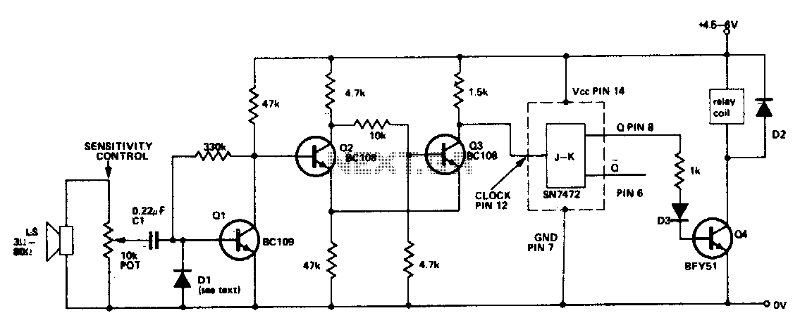
This circuit activates a relay in response to sounds of sufficient intensity. A single clap of the hands will switch the relay in one direction, while a second clap will return the circuit to its original state. Q2 and...
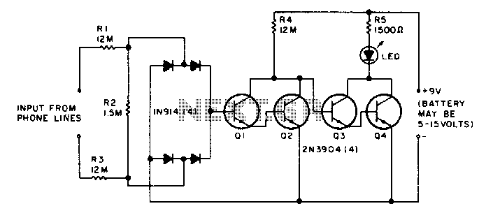
The LED flickers when the phone is ringing or being dialed. It glows steadily when the phone is off the hook. The described circuit involves an LED indicator that serves two primary functions based on the state of the phone....
This circuit operates on the ringing voltage of the telephone to trigger a tape recorder to record messages. It can be made to latch using extra contacts if the tape recorder requires a constant-contact closure. The circuit utilizes the ringing...
Christmas is approaching, and it is the time of year when electronics students and hobbyists consider creating a Christmas circuit for their homes, particularly one that features flashing lights. Numerous circuits and kits are available that can flash various...