
Microcontroller driving a Joule Thief circuit
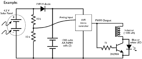
The circuit described utilizes a microcontroller to generate a PWM signal, which is an effective method for controlling the brightness of an LED. The Joule Thief is a simple DC-DC converter that steps up low voltage inputs, making it suitable for applications where battery life is crucial, such as powering LEDs from a single AA or AAA battery.
In this configuration, the microcontroller outputs a PWM signal that modulates the duty cycle, thereby controlling the average power delivered to the Joule Thief circuit. The Joule Thief typically consists of a few key components: a transistor, an inductor, a diode, and a capacitor. The transistor acts as a switch, turning on and off rapidly in response to the PWM signal. The inductor stores energy when the transistor is on and releases it to the output when the transistor turns off, effectively boosting the voltage to a level sufficient to power the white LED.
The diode in the circuit ensures that the current flows in one direction, preventing backflow into the Joule Thief circuit. The capacitor helps to smooth out the output voltage, providing a stable power supply to the LED. By adjusting the PWM frequency and duty cycle, the brightness of the LED can be finely tuned, allowing for dynamic control based on user input or environmental conditions.
Overall, this schematic illustrates an efficient method of driving an LED using minimal power while maximizing brightness through the clever use of PWM and a Joule Thief voltage booster.In this example we have the PWM (pulse-width modulation) output of the microcontroller driving a Joule Thief style voltage booster to run the white LED. 🔗 External reference
Related Circuits
This simple-to-construct water fishing thermometer circuit is intended for use in sports applications, such as fishing contests. A sensor measures... This water fishing thermometer circuit is designed to provide accurate temperature readings of water, making it an essential tool for...
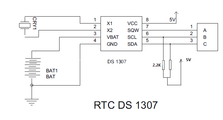
Steps involved in interfacing a Real-Time Clock (RTC) with a microcontroller. The RTC remains powered even when the device is turned off. The microcontroller must interface with the RTC to retrieve the data. To interface an RTC with a microcontroller,...
An automatic humidifier can be utilized for humidity control in households, hatcheries, poultry farms, or juvenile poultry houses. When the humidity level falls below 50%, the automatic humidifier activates to maintain a specific humidity level that is beneficial for...
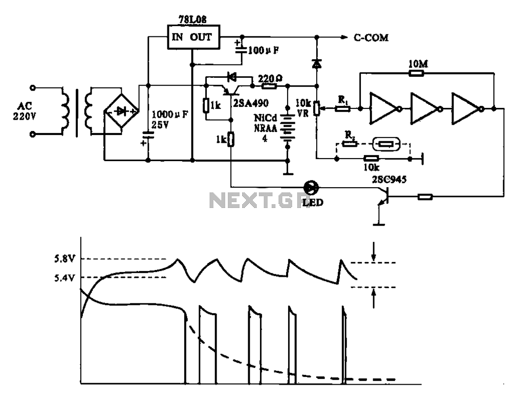
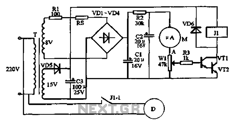
Fast charging circuit that illustrates voltage and current waveforms along with the configuration of the fast charge circuit for the charger. The detection and control circuit consists of three inverters (GMOS) from integrated circuits, enabling automatic control functions. The fast...
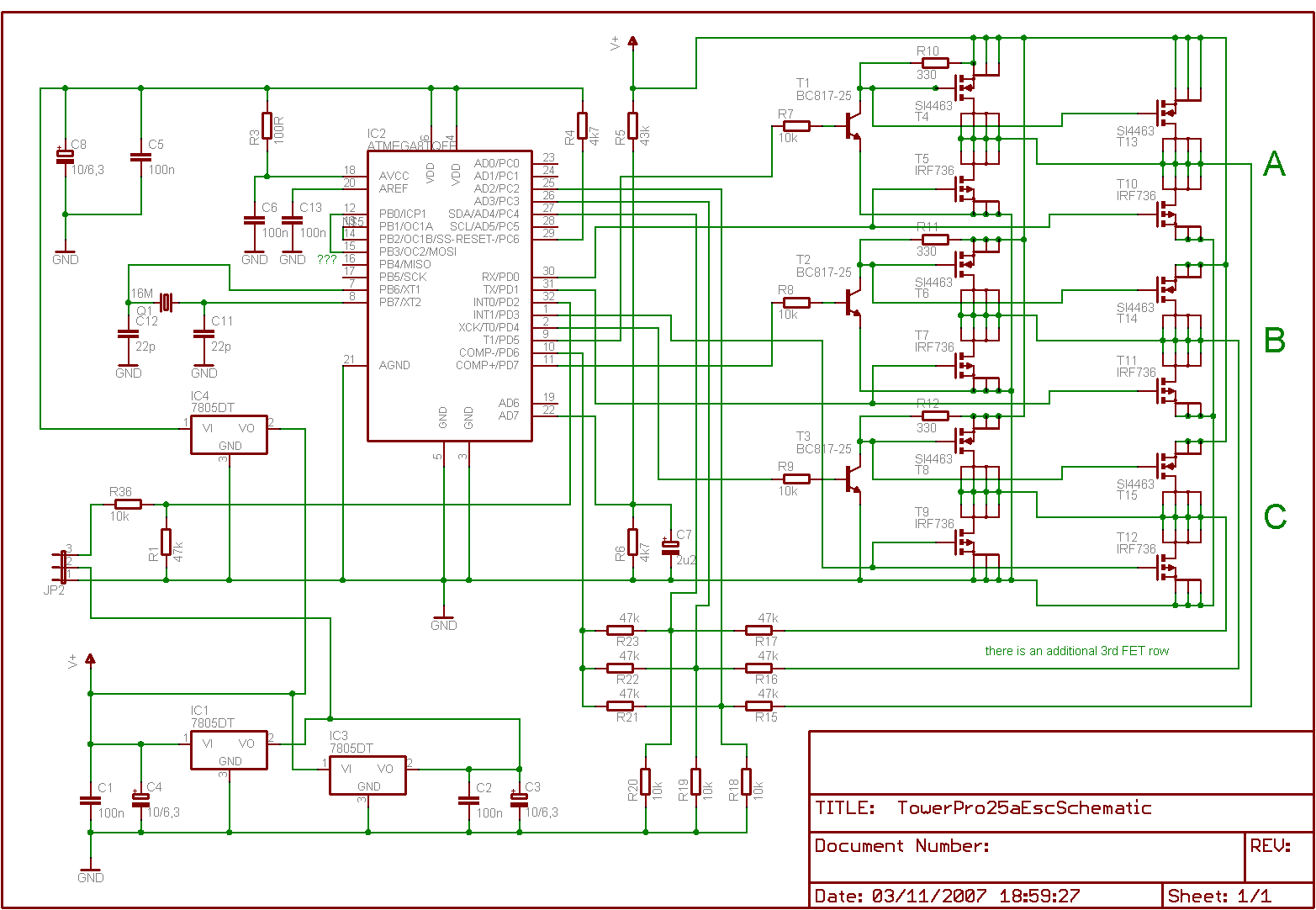
Is it feasible to eliminate the Electronic Speed Controllers (ESCs) from a multicopter configuration and substitute them with a single circuit board to control all the motors? The current setup consists of eight motors, each requiring an individual ESC,...
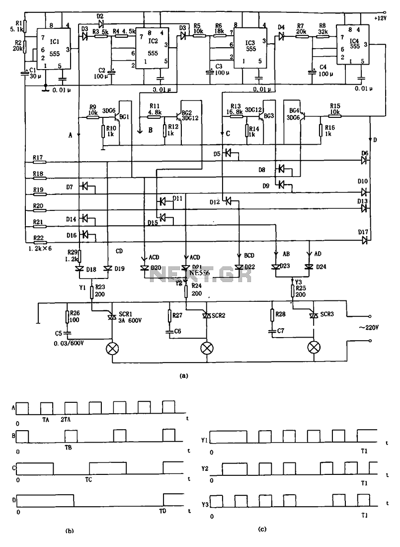
The decorative lamp control circuit is illustrated in the figure. The controller comprises a pulse generator, a frequency divider, a matrix circuit, and a thyristor control circuit. Components IC1, R1, R2, C1, and others form a multivibrator where the...
Warning: include(partials/cookie-banner.php): Failed to open stream: Permission denied in /var/www/html/nextgr/view-circuit.php on line 713
Warning: include(): Failed opening 'partials/cookie-banner.php' for inclusion (include_path='.:/usr/share/php') in /var/www/html/nextgr/view-circuit.php on line 713