
Interfacing RTC with Microcontroller
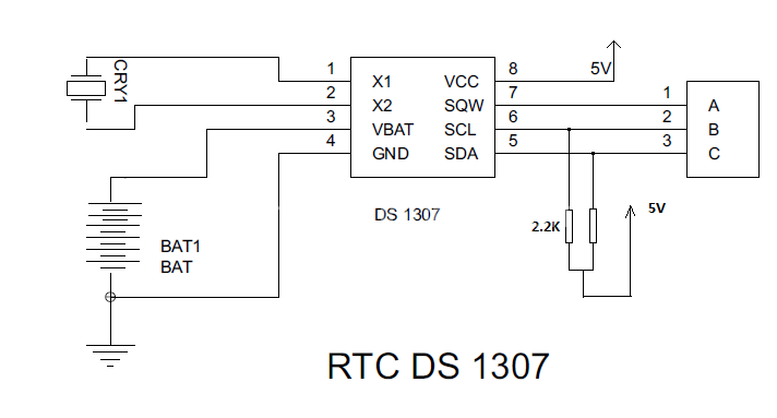
To interface an RTC with a microcontroller, several steps must be followed to ensure proper communication and data retrieval. The RTC is typically powered by a backup battery, allowing it to maintain accurate timekeeping even when the main power is off.
1. **Component Selection**: Choose an appropriate RTC chip, such as the DS3231 or PCF8563, which supports I2C or SPI communication protocols. Ensure compatibility with the microcontroller being used.
2. **Power Supply**: Connect the RTC to a suitable power supply. The VCC pin of the RTC should be connected to the power source, while the ground (GND) pin should be connected to the common ground of the microcontroller.
3. **Communication Interface**: Depending on the chosen RTC, connect the communication pins. For I2C, connect the SDA (data line) and SCL (clock line) pins of the RTC to the corresponding pins on the microcontroller. For SPI, connect the MOSI, MISO, SCK, and CS pins accordingly.
4. **Pull-up Resistors**: If using I2C, it is crucial to include pull-up resistors (typically 4.7kΩ) on the SDA and SCL lines to ensure proper signal levels.
5. **Microcontroller Configuration**: Configure the microcontroller’s I2C or SPI interface in the firmware. This includes setting the correct clock frequency and initializing the communication protocol.
6. **Data Retrieval**: Implement the necessary code to read the time and date data from the RTC. This typically involves sending a command to the RTC to request the current time and then reading the response back into the microcontroller.
7. **Continuous Operation**: If required, set up an interrupt or a polling mechanism to periodically check the RTC for updates or to synchronize the microcontroller's time with the RTC.
8. **Testing**: Finally, test the entire setup to ensure that the RTC is functioning correctly and that the microcontroller can successfully read the time data. This may involve debugging communication issues or verifying the accuracy of the timekeeping.
By following these steps, a reliable interface between the RTC and the microcontroller can be established, allowing for accurate timekeeping in various applications.steps involved in interfacing RTC with Microcontroller. There is a RTC that is kept ON even even is the device is turned OFF. Microcontroller has to interface the RTC to get the data.. 🔗 External reference
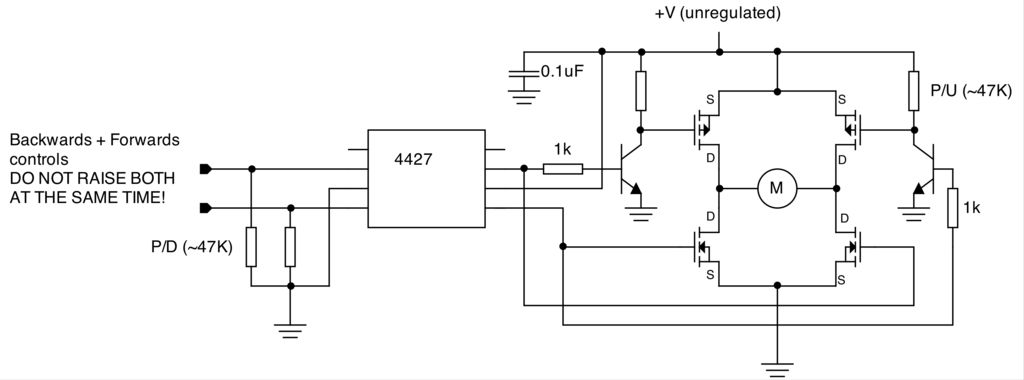
Related Circuits
To create a versatile and generic microcontroller board, the information provided thus far is sufficient. It covers the essential components needed to achieve this. The design of a microcontroller board requires careful consideration of various factors to ensure versatility and...
A slice of the SM2965 includes a canonical 80C32 microcontroller, FLASH memory, E2PROM (28SF512), SRAM for static data storage, and a watchdog timer (WDT). The cost performance of the SM2965 is notably high. This device is designed as a...
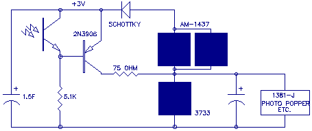
Here's a circuit diagram for Bob's "Vore-N-More" circuit containing the SmartCap solar engine: In this diagram, the "SmartCap" is just the 1.5 F storage capacitor, phototransistor, 2N3906 transistor, and 5.1K bias resistor. The idea is that after charging, a loss...
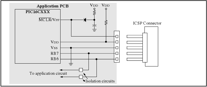
The programmer utilizes a serial signaling scheme to program the chip while it is in-circuit. The signaling is transmitted through the programming clock (PGC or ICSPCLK) and the programming data (PGD or ICSPDAT) pins. Additionally, the MCLR/VPP pin serves...

The LED running light project can be easily implemented using microcontrollers, particularly the Microchip PIC microcontroller. This project utilizes the PIC16F877A microcontroller, which features a 40-pin IC configuration, with LEDs connected to port B. The LEDs twinkle in accordance...
This instructable is categorized under 13 - 18 in the National Robotics Week Robot Contest. The National Robotics Week Robot Contest encourages innovation and creativity in robotics among participants aged 13 to 18. This category represents a significant opportunity for...