
circuit board for throttle control
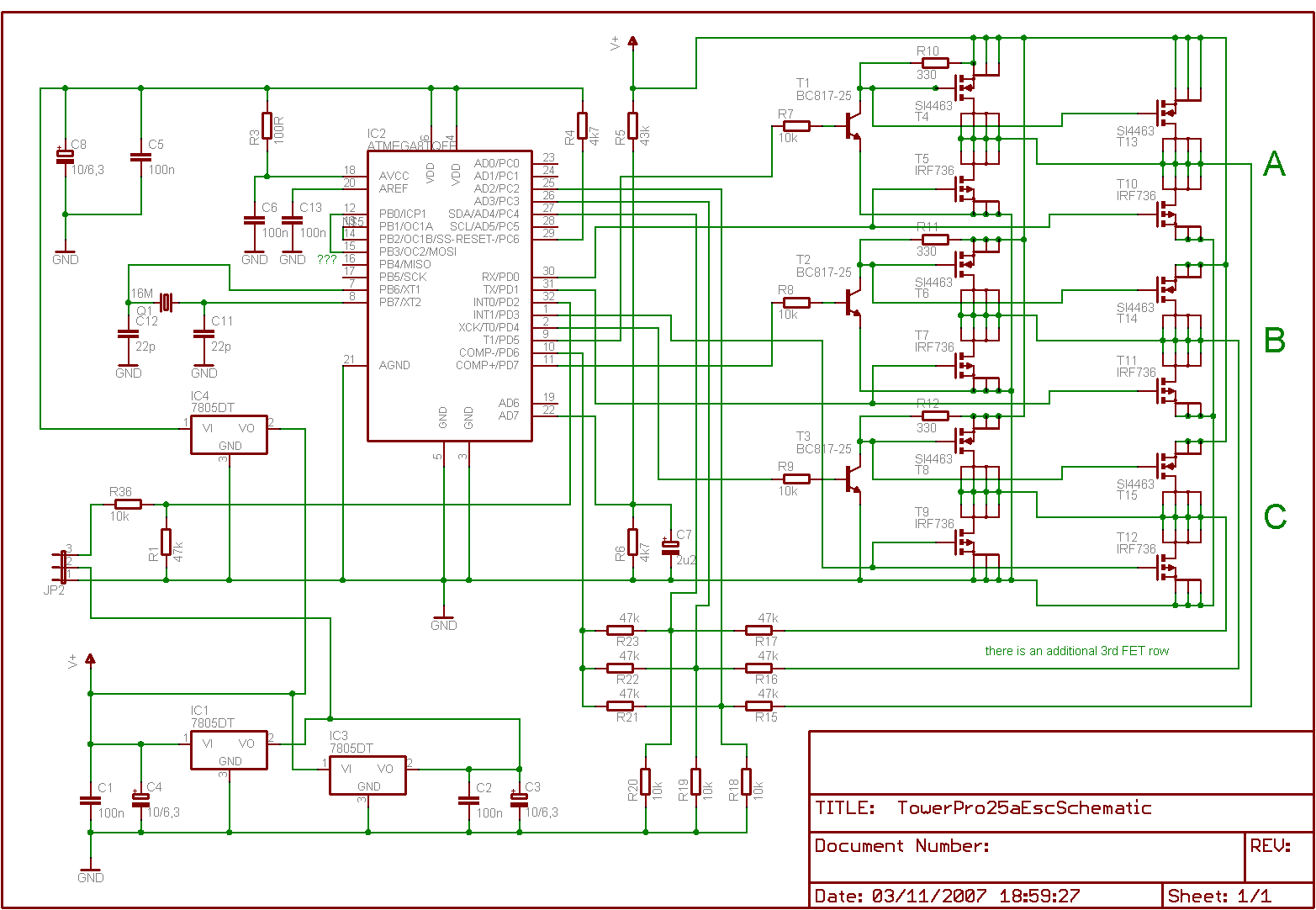
The proposal to consolidate the control of multiple motors in a multicopter setup into a single circuit board presents several engineering challenges and opportunities. A single circuit board design would ideally integrate the functionalities of multiple ESCs into one unit, thereby reducing weight, minimizing potential points of failure, and potentially lowering costs.
The circuit board would require a microcontroller capable of managing the throttle signals for all motors simultaneously. This microcontroller should be programmed to interpret the input from the flight controller, which typically provides commands based on pilot input or autonomous flight algorithms. Each motor would still need to be driven by a power stage capable of handling the current and voltage requirements, which could be achieved through high-efficiency MOSFETs arranged in a bridge configuration.
Additionally, the circuit board would need to incorporate robust thermal management solutions to dissipate heat generated during operation, as multiple motors will demand significant power. Implementing current sensing for each motor could enhance performance monitoring and provide feedback to the flight controller, allowing for real-time adjustments to ensure optimal performance and safety.
Safety features should also be considered in the design, such as overcurrent protection, thermal shutdown, and fail-safe mechanisms to ensure that the multicopter can land safely in the event of a malfunction.
In summary, while the integration of ESC functions into a single circuit board for a multicopter is technically feasible and could yield numerous benefits, it requires careful consideration of power management, thermal dissipation, and safety protocols to ensure reliable operation.Would it be possible to remove the ESCS from a multicopter setup and replace them with a 1 single circuit board to throttle all the engines? I have a 8 motor setup wich is 8 ESCS wich is 8times the way and 8 times the possibility of failure or broken down ESCS.
For the price those ESCS costs coudent we design a circuit board that manages to throttle the motors from any setup by itselfs? I believe draganfly company is using this they have a very small circuit board that controls the motors.
🔗 External reference
Related Circuits
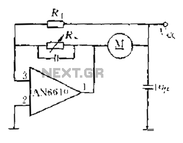
AN6610 Application Circuit operates as follows: When the supply voltage (Vcc) changes due to mechanical load variations, it can affect the motor speed. The motor speed is proportional to the back electromotive force (EMF). Consequently, the voltage across the...
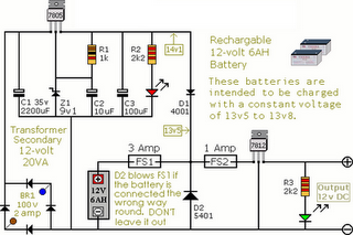
The following circuit illustrates an Alarm Power Supply Circuit Diagram. Features include a 1-amp current output, suitable for a Modular Burglar Alarm operating at 12 volts. The Alarm Power Supply Circuit is designed to provide a stable and reliable power...
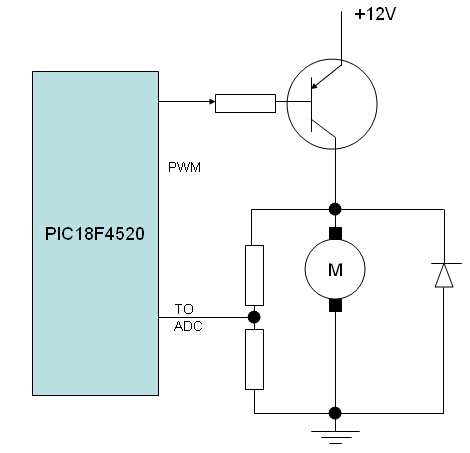
A speed closed-loop control system for a DC motor utilizes back EMF sensing. To implement this, a DC motor is operated in one direction, substituting the LED with the motor and omitting the current limit resistor. It is important...
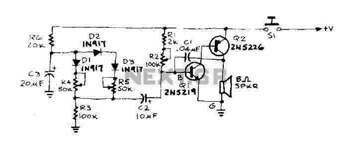
When the door is pushed, a whisper is heard that transitions to a higher frequency. The oscillator frequency is determined by the audio frequency coupling capacitance, C1, and the resistance connected between the base of transistor Q1 and ground....
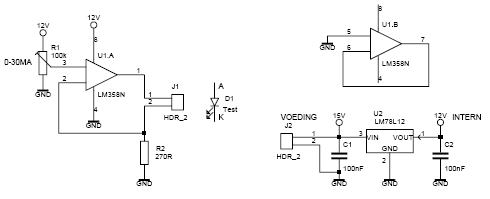
This led tester uses a power switched op-amp. The control range is about 0-30mA. Thus, all test and standard LEDs, the voltage across the LED to read. The power supply is an example lab power supply at least 15V,...
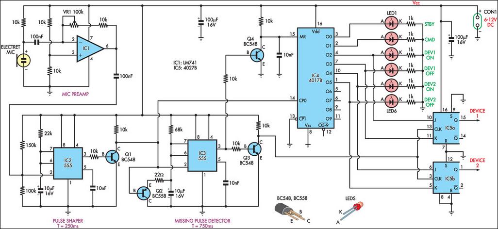
This circuit can switch two or more devices on and off in response to a series of rapid handclaps. The claps are detected by an electret microphone and amplified by a 741 operational amplifier (IC1). IC1 is configured as...