
microcontroller driving a relay with transistor and Opto-isolator

The circuit described involves the integration of a relay control system utilizing an STM32 microcontroller, a 4N33 opto-isolator, and an MPS222 transistor. The STM32 microcontroller is programmed to control the relay via its GPIO pins. The 4N33 opto-isolator provides necessary electrical isolation between the microcontroller and the relay circuit, ensuring that any high voltages or currents do not affect the microcontroller's operation.
In the circuit, the relay coil requires a current of approximately 250 mA to operate effectively. The MPS222 transistor acts as a switching device, allowing the current to flow through the relay coil when activated by the opto-isolator. The opto-isolator's LED is driven by a GPIO pin configured in open-drain mode, which means it can only pull the line low and requires an external pull-up resistor to pull the line high when the GPIO is not active.
The issue of the relay inadvertently activating when the STM32 is disconnected is a critical consideration in circuit design. The absence of the R2 resistor, which is intended to provide a path to ground, can lead to undefined behavior in the circuit, potentially allowing the relay to turn on due to stray voltages or floating states on the GPIO pin. By adding the R2 resistor and properly grounding it, the GPIO pin can be pulled to a defined low state when the microcontroller is disconnected, thereby preventing the relay from being activated unintentionally.
In conclusion, the addition of the R2 resistor is a recommended solution to mitigate the risk of the relay turning on due to disconnection of the STM32 microcontroller. Implementing this change will enhance the reliability and safety of the relay control circuit.Controlling a relay with stm32 micro controller. For the isolation I have used a 4N33 opto-isolator. As my relay coil needs around 250 mA, I used a mps222 transistor. I figured that the logic gets inverted when I used the gpio as the source voltage for the opto-isolator led. I just used a pull up instead and connected the other end of the led part to the gpio. Gpio is open drain, I will drain around 3mA in the pin. I do not have the R2 resistor grounded at this moment. My problem is if in case my stm gets disconnected then my relay will be turned on - which I want to avoid. Could anyone please tell me if adding this R2 will fix the issue 🔗 External reference
Related Circuits
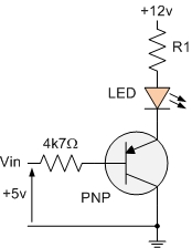
The PNP transistor is the exact opposite of the NPN transistor discussed in the previous tutorial. In this type of transistor construction, the two diodes are reversed compared to the NPN type, resulting in a Positive-Negative-Positive configuration, with the...

This project is a microcontroller-based college automation system aimed at addressing the challenges faced in educational institutions. It replaces the conventional notice board with an automated device that allows users to both hear and read the information being announced...

This design uses a smart card to enable a relay. A Nutchip recognizes its mating smart card among thousand similar ones, because you choose the code to be programmed in the card's memory. No specialized knowledge is necessary, as...
The simple FM radio circuit was overlooked during the transition from vacuum tubes to transistors. In the late 1950s and early 1960s, several construction articles were published on building a straightforward superregenerative FM radio. After extensive research into these...
This circuit is designed to drive a relay coil using a low power output, typically from an integrated circuit (IC) such as a 555 timer or a TTL/CMOS device. It facilitates the switching of high loads or loads requiring...

Derating is the method of reducing a device's operational limits as temperature increases, specifically concerning the device's power dissipation in relation to rising ambient temperature. Ambient temperature refers to the air temperature measured below a semiconductor device in an...