
build one transistor fm radio
The superregenerative FM radio circuit operates on the principle of regenerative feedback, allowing for amplification of weak radio signals. The circuit's core components include the variable capacitor (C3), the inductor (L1), and the audio amplifier (D1). The variable capacitor is essential for tuning into different frequencies, while the inductor not only helps establish the frequency of oscillation but also acts as an antenna for signal reception. The careful arrangement of these components is crucial, as proximity can affect performance due to stray capacitance and interference.
The audio amplifier can be selected based on availability and desired performance characteristics. The LM386 and TDA7052 are both suitable choices, with the TDA7052 being particularly well-suited for low-voltage applications. The circuit's gain can be adjusted to ensure adequate audio output while maintaining stability and preventing distortion.
For assembly, precise construction techniques are recommended. The winding of the inductor should be uniform, and the spacing between turns should be consistent to minimize parasitic capacitance. Proper soldering techniques will ensure reliable connections and enhance the overall performance of the circuit. Testing and troubleshooting should be conducted carefully, with attention paid to the placement of components and the tuning process, as these factors significantly influence the radio's ability to receive signals effectively.The simple FM radio circuit got lost during the transition from vacuum tubes to transistors. In the late 1950s and early 1960s there were several construction articles on building a simple superregenerative FM radio. After exhaustive research into the early articles and some key assistance from a moder n day guru in regenerative circuit design, I have developed this simple radio kit. It is a remarkable circuit. It is sensitive, selective, and has enough audio drive for an earphone. Read more about theory behind this radio on the low-tech FM page. Except the the circuit board and battery, all parts are from Mouser Electronics. A complete parts list with stock numbers is listed below. The circuit board is available through FAR Circuits. The variable capacitoPrinted circuit board Connect the two sections of the variable capacitor (C3) in series to linearize the tuning somewhat. That is, use the connections on either end of C3 and don`t use the middle lead. L2, the RF choke should not be near a ground. The same is true for L1. Capacitance to ground will disturb the feedback. The gain is just enough to drive an earphone. If you live too far away from radio stations, you might have trouble hearing one. There is no option here for an external antenna (that would require and extra transistor). If you want a little more audio gain, or you cannot locate a TL431CLP chip, you can use some other audio amplifier in the circuit where pins 1 and 2 of D1 normally connect.
You can use an LM386 or a TDA7052 audio amplifier. Quasar DIY project kit #3027 is a complete TDA7052 audio amplifier kit and it works fine in this application. Because this is a superregenerative design, component layout can be very important. The tuning capacitor, C3, has three leads. Only the outer two leads are used; the middle lead of C3 is not connected. Arrange L1 fairly close to C3, but keep it away from where your hand will be. If your hand is too close to L1 while you tune the radio, it will make tuning very difficult. L1 sets the frequency of the radio, acts as the antenna, and is the primary adjustment for super-regeneration.
Although it has many important jobs, it is easy to construct. Get any cylindrical object that is just under 1/2 inch (13 mm) in diameter. I used a thick pencil from my son`s grade school class, but a magic marker or large drill bit work just fine. #20 bare solid wire works the best, but any wire that holds its shape will do. Wind 6 turns tightly, side-by-side, on the cylinder, then slip the wire off. Spread the windings apart from each other so the whole coil is just under an inch (2. 5 cm) long. Find the midpoint and solder a small wire for C2 there. Mount the ends of the wire on your circuit board keeping some clearance between the coil and the circuit board.
C3 does not come with a knob and I have not found a source. A knob is important to keep your hand away from the capacitor and coil when you tune in stations. The solution is to use a #4 nylon screw. Twist the nylon screw into the threads of the C3 tuning handle. The #4 screw is the wrong thread pitch and will jam (bind) in the threads. This is what you want to happen. Tighten the screw just enough so it stays put as you tune the capacitor. The resulting arrangement works quite well. If the radio is wired correctly, there are three possible things you can hear when you turn it on: 1) a radio station, 2) a rushing noise, 3) a squeal, and 4) nothing. If you got a radio station, you are in good shape. Use another FM radio to see where you are on the FM band. You can change the tuning range of C3 by squeezing L1 or change C1. If you hear a rushing noise, you will probably be able to tune in a station. Try the tuning control and see what you get. If you hear a squeal or hear nothing, then the circuit is oscillating too little or too much. Try spreading or compressing L1. Double check 🔗 External reference
Related Circuits
This circuit will flash a bright red LED (5000 mcd) as an attention-getting device or fake car alarm. Component values are not critical, and other transistors may be used. The flash duration is determined by R2 and C1 and...
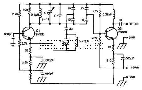
This oscillator circuit utilizes a 5th overtone crystal operating within the 85 to 106 MHz frequency range. The component Y1 represents the crystal. The circuit was initially designed for frequency control in a microwave oscillator. The oscillator circuit leveraging a...
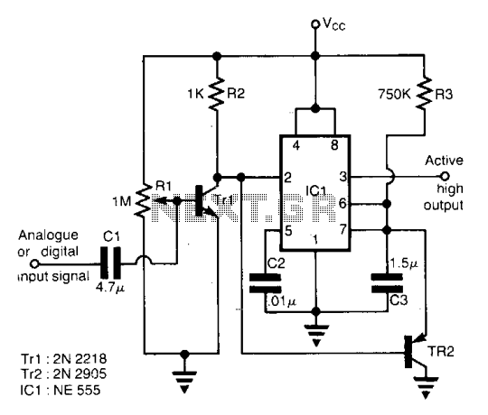
The circuit is designed for speech activity detection in telephone lines. This detection is particularly beneficial for half-duplex conversations between two stations, for simultaneous transmission of voice and data over the same pair of cables by interspersing data within...
A more affordable method to create or purchase a device that offers similar functionality. It does not necessarily need to be remote-controlled if it can be programmed to activate at specific times. This description suggests the development of a cost-effective...
A telephone ringer capable of making any mains-powered device operate from the ringer of a fixed line telephone. This device allows the control of a high-powered siren or horn to amplify the low-level sound of a telephone, making it...
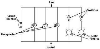
Each component of the circuit is represented in a simple block form with corresponding labels for identification, using no special symbols or language. The interconnections between these components are depicted by solid lines. The block diagrams can be read...