
Microcontroller measures heart rate through fingertip
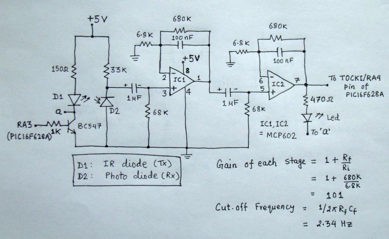
The circuit begins with a photodiode that captures the reflected IR signals. The photodiode operates by generating a small current proportional to the intensity of the incoming IR light. This current is typically weak and requires amplification and conditioning to be useful for further processing.
The signal conditioning circuit includes a low-pass filter to eliminate high-frequency noise that may interfere with the desired signal. This filter can be implemented using passive components such as resistors and capacitors or through active components like operational amplifiers configured in a filter topology. Following the filtering stage, an amplifier circuit is employed to boost the signal to a suitable level for subsequent processing.
The amplifier may utilize a non-inverting configuration to ensure that the signal phase is maintained while providing the necessary gain. The gain can be adjusted by selecting appropriate resistor values in the feedback loop of the operational amplifier.
After amplification, the conditioned signal can be further processed by an analog-to-digital converter (ADC) if digital signal processing is required. This allows for the integration of the system with microcontrollers or digital signal processors, enabling advanced functionalities such as signal analysis, data logging, or real-time monitoring.
Overall, the design of the signal conditioning circuit is critical for ensuring accurate and reliable detection of the reflected IR signals, making it a vital component in various applications such as proximity sensing, object detection, and automated control systems.The reflected IR signal detected by the photo diode is fed to a signal conditioning circuit that filters the unwanted signals and boost the desired pu.. 🔗 External reference
Related Circuits
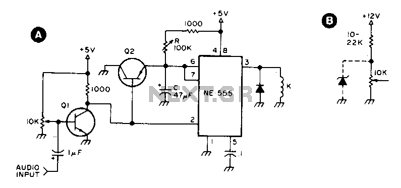
Q1 and Q2 are general-purpose transistors. The 10 kΩ input potentiometer is adjusted to a point just short of where Q1 turns on, as indicated by relay K engaging. K is any 5 V reed relay. With the specified...
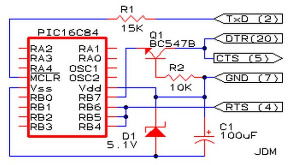
Affordable PIC Programmer. This programmer is compatible solely with the PIC16F84 microcontroller. It is reliable, as it rarely encounters errors, and functions well with nearly all computer systems, in contrast to some alternatives. The PIC programmer designed for the PIC16F84...
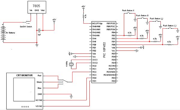
The objective of this project is to develop a device capable of outputting VGA signals to a CRT monitor to display figures, text, and characters. The project involves designing a circuit that generates standard VGA signals, which include separate horizontal...
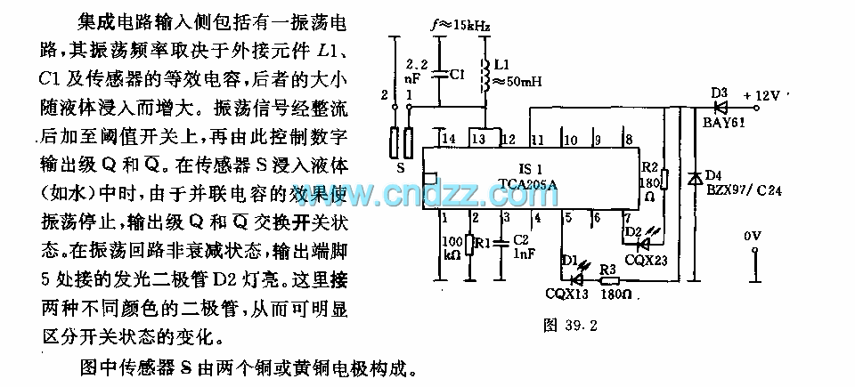
The integrated circuit input side contains an oscillating circuit, where the oscillation frequency is determined by the external components L1, C1, and the sensor's equivalent capacitance. The equivalent capacitance increases as the sensor is immersed in liquid. The oscillating...
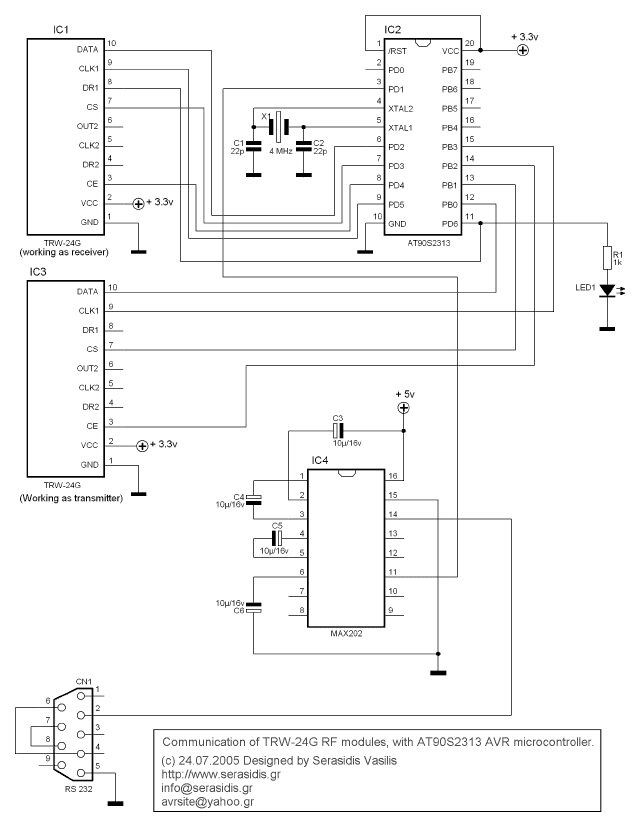
The TRW-24G connector pins are quite small, approximately 1mm apart. To address this issue, an adaptor PCB has been ordered to convert the small connector of the RF module to a standard pin connector. The pin arrangement of the...
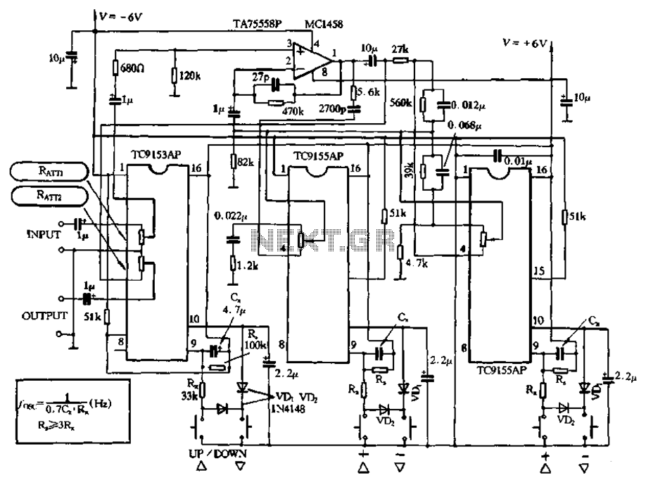
Figure 4-18 illustrates a volume potentiometer T (Xi 153AP) and a tone potentiometer T (155AP) that make up a volume and tone control circuit. This circuit includes Rx and Cx as clock oscillation elements, with values selectable based on...