
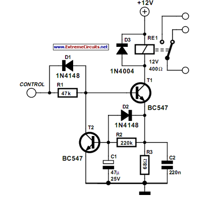
Audio operated relay
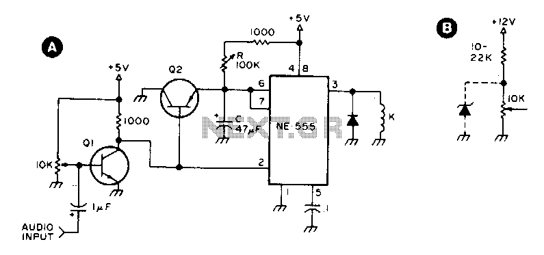
The circuit employs two general-purpose transistors, Q1 and Q2, which serve as the primary switching elements. The input control is facilitated by a 10 kΩ potentiometer, which allows for fine adjustment of the input signal. This potentiometer is critical in setting the threshold at which transistor Q1 activates, thereby energizing the relay K. The relay used in this configuration is a 5 V reed relay, which is suitable for low-power applications.
The timing characteristics of this circuit are determined by the resistor R and capacitor C values. A resistor value of 100 kΩ in conjunction with a capacitor of 47 µF creates an RC time constant that yields timing delays ranging from 5 seconds to slightly over 5 seconds. This delay can be critical in applications such as timing circuits or delay switches, where a specific on-off sequence is required.
When operating the circuit with a 12 V power supply, it is essential to include a 22 Ω series resistor with the 10 kΩ potentiometer. This adjustment is necessary to accommodate the higher voltage and to ensure that the input current remains within safe limits for the transistors and the relay. Additionally, a 12 V reed relay must be used in this configuration to ensure proper operation, as the relay's coil must be compatible with the supply voltage to function correctly.
Overall, this circuit design provides a flexible solution for applications requiring timed relay activation, with the potential for adjustments based on varying supply voltages. Proper selection of components and values is crucial for achieving the desired performance and reliability in practical implementations.Ql and Q2 are general purpose transistors. The 10 K input pot is adjusted to a point just short of where Ql turns on as indicated by K pulling in. K is any 5 V reed relay. With the values shown for R (100 K) and C (47 µf), timing values from 5 to slightly over 5 seconds can be achieved
B shows the addition of a 22 ? series resistor to the 10K input pot if a 12 V supply is used. A suitable 12 V reed relay must be used at K. 🔗 External reference
Related Circuits
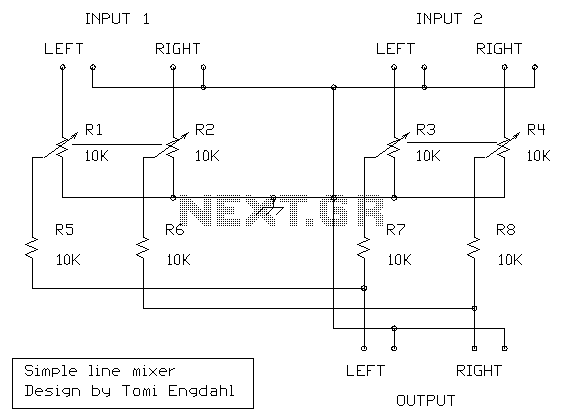
I designed this circuit for one friend of mine to be used as a small portable DJ mixer. The circuit is an audio mixer circuit so simple as it can be. There are two dual logarithmic potentiometers in the...
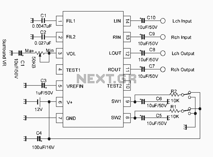
The NJM2701 3D surround sound audio processor integrated circuit can be designed into a very simple 3D surround sound system. The NJM2701 reproduces 3D surround sound using only two speakers and is suitable for various audio applications, including micro-components,...
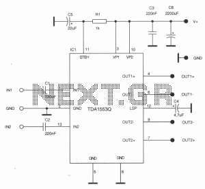
This stereo amplifier is designed for automotive applications and can deliver up to 2 x 22W using a single TDA1557Q or TDA1553Q from Philips. The stereo amplifier circuit utilizes the TDA1557Q or TDA1553Q integrated circuit, which is a high-performance...
Some relays will become warm if they remain energized for some time. The circuit shown here will actuate the relay as before but then reduce the hold current. The described circuit addresses the issue of heat generation in relays due...
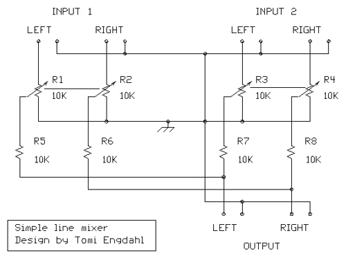
The mixer circuit described features three line inputs and three microphone inputs. The microphone inputs are designed for low impedance dynamic microphones with a range of 200 to 1000 ohms. Alternatively, an electret condenser microphone (ECM) can be used,...
A few years ago, a decision was made to eventually replace a decades-old Nakamichi stereo system with a more mobile-friendly alternative. It became apparent that Class-D and Class-E switching amplifiers, which had been researched in the 1970s, were experiencing...