
4017 IC For Flip-Flop Timer Circuit DIagram
The 4017 decade counter IC is commonly used in timer and counting applications. In this circuit, the 4017 is configured to operate as a flip-flop timer. The push-button switch (S1) serves as the trigger mechanism for initiating the timing sequence. When pressed, S1 allows capacitor (C1) to discharge through resistor (R2), creating a timing interval based on the RC time constant defined by the values of R2 and C1.
The output of the 4017 IC can be connected to various load devices, such as LEDs or relays, to indicate the timing intervals visually or to control other electronic components. The timing can be adjusted by changing the values of R2 and C1, allowing for flexibility in the duration of the timer.
Additionally, the circuit may include other components such as diodes for protection against reverse polarity, or additional resistors to fine-tune the timing characteristics. The design ensures that the circuit operates reliably and provides a clear indication of the timing cycle through the output states of the 4017 IC.This circuit shows about 4017 IC For Flip-Flop Timer Circuit DIagram. Features: Push-button S1 will discharge capacitor C1 through R2. Component: .. 🔗 External reference
Related Circuits
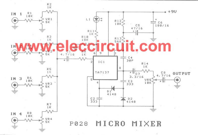
A micro mixer circuit is designed to be simple, affordable, compact, and versatile. This circuit can mix up to four input channels, including microphone signals, FM tuners, AUX, and other signals, as illustrated in Figure 1. The operation begins...
The output of the transformer has been calculated to be 125 times higher than the input, based on the ratio of 1000 to 8. Given an input of 12V, the expected output should be 1500V, although there is some...
This DC to DC converter increases a DC voltage to nearly double its original value and is useful for elevating the output voltage of solar batteries to the required level. The DC to DC converter operates on the principle of...
This circuit automatically controls the headlight of a motorcycle, turning it on and off independently of the light and ignition switches, as long as the battery is fully charged. The initial stage employs a 220-ohm resistor and ZD1 to...
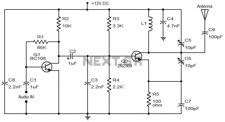
Numerous FM transmitter circuits have been published, and this is another example of a simple two-transistor FM transmitter. The first stage of the circuit is a preamplifier based on transistor Q1. This stage operates as a collector-to-base biased amplifier,...

This is a simple hobby circuit for a remote-controlled toy car. The primary component utilized is the IR sensor circuit, which includes a TSOP IR receiver. This receiver allows the user to start and stop the DC motor of...