
fan control circuit using ntc and tl082

The circuit described is an effective temperature-controlled fan speed regulator, utilizing a combination of resistors, potentiometers, an NTC thermistor, and a MOSFET to modulate fan speed based on temperature changes. The NTC thermistor provides a temperature-dependent resistance that decreases as the temperature increases, allowing for precise control over the fan's operation. The use of the TL082 op-amp facilitates signal amplification and processing, ensuring that the control signals are robust enough to drive the MOSFET effectively.
The IRF-510 MOSFET acts as a switch that regulates the power delivered to the fan. Its gate voltage controls the amount of current flowing through the device, with higher gate voltages resulting in greater current flow. This characteristic allows the circuit to respond dynamically to temperature changes, adjusting fan speeds accordingly. The inclusion of a diode (D1) serves to protect the circuit from back EMF generated by the fan’s inductive load when the MOSFET is turned off, ensuring circuit stability and longevity.
In practical implementation, careful calibration of the potentiometers (P1 and P2) is essential to achieve the desired fan performance. The circuit can be integrated into various applications where temperature regulation is crucial, such as in computer cooling systems, HVAC systems, or any environment where heat dissipation is necessary. The design considerations, including heat management for the MOSFET and proper component ratings, are critical for reliable operation. Overall, this schematic provides a comprehensive solution for automated fan speed control based on ambient temperature conditions.R1 15k ohm resistor. NTC Thermistor- 10k ohm, sold at Radio Shack in the states. P1 10k ohm potentiometer - sets the low speed(voltage) of the fans at the cool temperature. P2 50K ohm potentiometer - sets the gain of the circuit - how fast the voltage will rise to full output when the temp is higher. TL082 a op-amp that I had handy, most any singl e voltage op-amp should work. The TL082 is a dual op-amp if you want more then one controller on a board. note that the power and ground connections for the op-amp are not shown on the schematic. R2 - The TL082 is a fast op-amp, needed R2 to reduce oscillation. IRF-510 A 4 amp mos-fet in a TO-220 case. Bascially as the voltage on the gate rises the mos-fet will conduct more current. note 1 there are also IRF-520 and 530 versions that will handle more current. note 2 Even at 5 watts the mos-fet will disapate some heat and will need to be heat-sinked or at least in the air flow path. the large metal part of the fet will be at drain(D) voltage level. Do not attach to case. D1, almost any diode, 1N4001 should work, it conducts back around the fan when the mosfet turns off. As the fan continues spinning it will produce a voltage on the drain lead of the fet. D1 will limit that voltage. Adjustment, easiest if you have a voltmeter but can be done without. Get the thermistor at room temp. Adjust P1 for the low speed that you want your fans to run at. Heat the thermistor to the high temp you want the fans at full speed. ( I stuck it under my tongue) Adjust P2 until the fans are at full speed( with voltmeter the highest voltage you can get) then adjust P2 until the speed/voltage just begins to drop off.
Most fan specs that I have seen show a low voltage limit of around 7 volts. Some of the smaller 80mm fans have a lower limit of 8 volts. If you set the low voltage to low the fans may stall until the thermistor heats up enough. Let me know if you build this circuit and how it works for you. corrected, single voltage op-amps should be used, OP-07 is a dual voltage. 🔗 External reference
Related Circuits
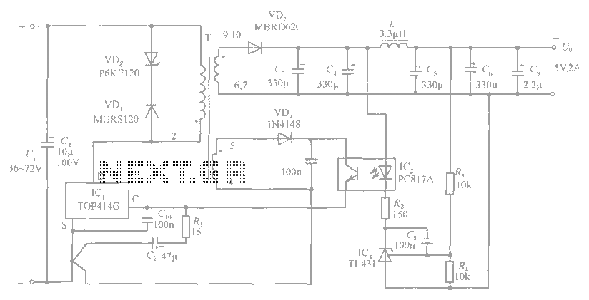
The circuit diagram includes an input filter capacitor C1 and a primary clamp composed of VDz and VD1. The resistor R1 is connected to the control terminal. C2 serves as a bypass capacitor. The TOP414GC-S is connected in parallel...
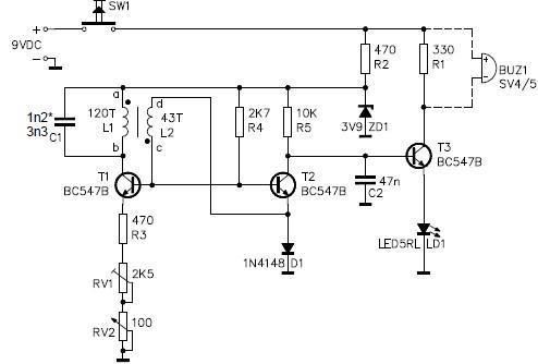
This metal detector circuit project is a simple design based on common electronic components. It utilizes transistors to provide a visual indication through an LED and an acoustic signal to alert users when metal is detected. To calibrate the...
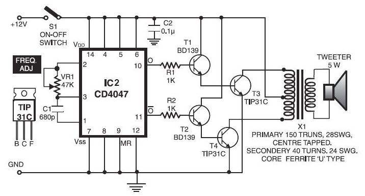
The electronic dog repellent circuit diagram below is a high-output ultrasonic transmitter primarily intended to act as a dog and cat repeller. The electronic dog repellent circuit utilizes a high-frequency ultrasonic transmitter to emit sound waves that are unpleasant to...
A simple USB FM transmitter that can be used to play audio files from an MP3 player or computer on a standard VHF FM radio by connecting it to a USB port. The circuit does not require any coils...
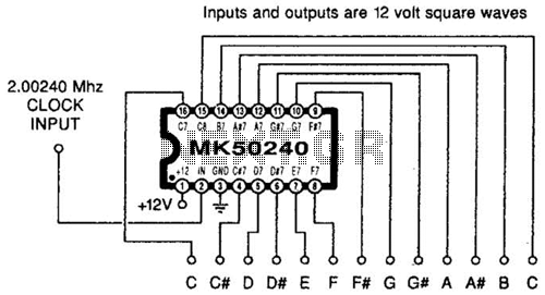
Using an MK50240, this circuit generates 12 top octave tones. The input and output lines can be separated using a binary divider IC to achieve the lower notes. Inputs and outputs are 12-volt square waves. The MK50240 is a specialized...
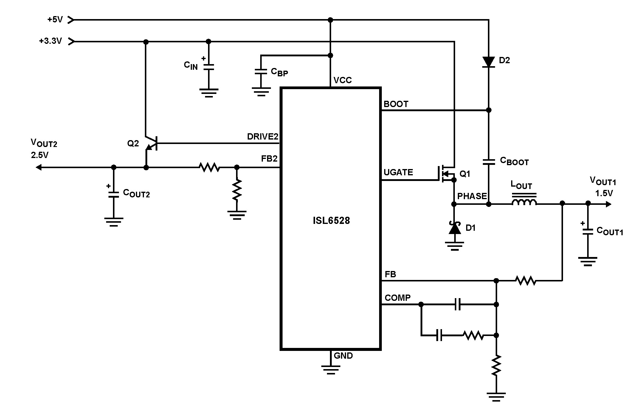
The ISL6528 offers power control and protection for two output voltages in high-performance graphics cards and other embedded processor applications. This dual-output controller drives an N-Channel MOSFET in a standard buck topology and an NPN pass transistor in a...