
Oscilloscope Xminilab-B on the microcontroller Atmel AVR ATXMEGA32A4

The Xminilab-B oscilloscope features a compact and efficient design that leverages the capabilities of the ATXMEGA32A4 microcontroller, which is known for its high performance and low power consumption. This microcontroller supports advanced analog and digital functionalities, making it suitable for a variety of applications in electronic testing and debugging.
The debug board is equipped with multiple input channels, allowing for the simultaneous observation of different signals. Each channel can handle a specific voltage range, and the oscilloscope is capable of displaying waveforms in real-time. The user interface is designed for ease of use, typically featuring a graphical display that presents the waveforms clearly, along with controls for adjusting time base and voltage scale.
Additionally, the Xminilab-B may incorporate features such as trigger functions, which allow users to stabilize repetitive waveforms for better analysis. It may also support data logging capabilities to capture and store signal data for further examination. The integration of the ATXMEGA32A4 microcontroller provides flexibility in programming and customization, enabling users to tailor the oscilloscope's functionality to meet specific testing requirements.
Overall, the Xminilab-B oscilloscope represents a valuable tool for engineers and developers, facilitating efficient debugging and analysis of electronic circuits. Its design reflects a combination of innovative technology and practical application, making it a noteworthy addition to the field of electronic instrumentation.Oscilloscope Xminilab-B on the microcontroller Atmel AVR ATXMEGA32A4 electro suite in rlocman The Gabotronis company produces debug board Oscilloscope Xminilab-B on the microcontroller Atmel AVR ATXMEGA32A4 electro suite. As we found in rlocman.ru, The Gabotronis company produces debug board.. 🔗 External reference
Related Circuits
This is an early test program (assembly source code) that was stored on the erasable programmable memory chip (EEPROM). Assembler programming is just one step above programming at the binary level. The described early test program utilizes assembly language, which...

AVR has two different programming modes called Parallel Programming Mode (Parallel Mode) and Serial Downloading Mode (ISP mode). In Parallel Mode, the programming is done using multiple data lines simultaneously, allowing for faster programming speeds. This mode is typically...
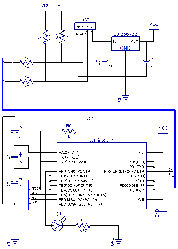
This is the second part of a USB tutorial for the ATtiny2313 microcontroller and the V-USB library. The first part covered how to derive 3.3V from USB to power circuits. In this section, the setup will be expanded with...
It is a miniature 10/100-MbBit Ethernet module that includes an integrated microcontroller. The price is less than $60. With its minimal dimensions of 1.38 in. x 2.16 in. (34.5 mm x 54 mm), the communications module can be used...
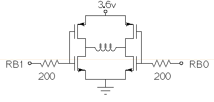
Drive a small (3.6V, <1A) brushed motor bidirectionally with a PIC microcontroller (MCU). The available space is extremely limited, so a single 3.6V power supply will be used for both the motor and the PIC, with minimal drive circuitry required. There is no dedicated motor driver IC that operates at this low voltage, making a discrete H-bridge the most suitable drive arrangement. The NXP PMV30UN and PMV32UP have been identified as suitable N-type and P-type drive MOSFETs. Since both the PIC and the motor share the same power supply, it is questioned whether it is possible to eliminate the usual driving circuitry for an H-bridge and connect the transistors directly to the MCU pins. Potential pitfalls of this approach should also be considered. To design a bidirectional motor drive circuit using a PIC microcontroller and a discrete H-bridge configuration, the following considerations must be taken into account. The H-bridge consists of four MOSFETs arranged in a configuration that allows current to flow through the motor in either direction, enabling bidirectional control. The NXP PMV30UN and PMV32UP MOSFETs are suitable candidates due to their low on-resistance and capability to operate at the required 3.6V supply voltage. The connections between the PIC MCU and the MOSFETs should be made with consideration of the gate drive requirements. Directly connecting the MOSFET gates to the MCU pins can be feasible, but it is essential to ensure that the MCU can provide sufficient gate drive voltage to fully turn on the MOSFETs. A typical threshold voltage for these MOSFETs is around 1V, so the output high level from the PIC should exceed this threshold to ensure efficient operation. It is also critical to incorporate pull-down resistors on the gate pins to prevent the MOSFETs from floating when the MCU is in a high-impedance state. This will help avoid unintended motor activation. Additionally, using gate resistors can help dampen any oscillations and limit inrush current during switching, which could potentially damage the MOSFETs or the MCU. Another consideration is the back EMF generated by the motor when it is switched off or when changing direction. This can induce voltage spikes that may damage the MCU or the MOSFETs. To mitigate this risk, flyback diodes should be placed in parallel with each MOSFET to provide a path for the back EMF, ensuring safe operation of the circuit. Thermal management is also a critical aspect of the design. Although the MOSFETs are rated for low on-resistance, continuous operation near their current limits can lead to significant heat generation. Adequate heat dissipation measures, such as heat sinks or thermal pads, should be considered. In summary, while it is possible to connect the MOSFETs directly to the MCU pins, careful attention must be given to gate drive requirements, protection against back EMF, and thermal management to ensure reliable and efficient operation of the bidirectional motor drive circuit.

This simple adapter utilizes an oscillator (567) to drive a counter (U2) and a switch (U3) that selects the output of one of four scope preamps (Q1/Q2 through Q7/Q8) and feeds it to buffer Q9 and output jack J1....