
Microphone Circuit-PC Sound Card

The microphone circuit described utilizes a composite amplifier design to enhance the performance of an electret microphone when interfaced with a PC's sound card. The circuit begins with the BC413B transistor, which is configured in a common emitter arrangement. This configuration is effective for amplifying the low-level audio signals generated by the electret microphone, which typically has a higher output impedance compared to dynamic microphones. The common emitter configuration allows for a significant gain, boosting the microphone's output signal to a more usable level for the sound card.
Following the BC413B, the circuit employs a BC547C transistor configured as an emitter follower. This stage serves to further buffer the amplified signal from the first stage while providing a low output impedance. The emitter follower is critical in this design, especially in applications where the microphone and associated circuitry are located at a distance from the sound card. The low output impedance reduces the potential for signal degradation over long cable runs and minimizes the susceptibility to noise pickup, which is particularly important in audio applications.
The design also emphasizes the importance of using a screened cable for the connection between the microphone circuit and the sound card. The shielding helps to protect the audio signal from electromagnetic interference and radio frequency interference, ensuring that the output remains clean and clear. Overall, this circuit effectively adapts an electret microphone for use with a standard PC sound card, providing a reliable solution for audio input applications.This microphone circuit was submitted by Lazar Pancic from Yugoslavia. The sound card for a PC generally has a microphone input, speaker output and sometimes line inputs and outputs. The mic input is designed for dynamic microphones only in impedance range of 200 to 600 ohms. Lazar has adapted the sound card to use a common electret microphone usi ng this circuit. He has made a composite amplifier using two transistors. The BC413B operates in common emitter to give a slight boost to the mic signal. This is followed by an emitter follower stage using the BC547C. This is necessary as the mic and circuit and battery will be some distance from the sound card, the low output impedance of the circuit and screened cable ensuring a clean signal with minimum noise pickup. 🔗 External reference
Related Circuits
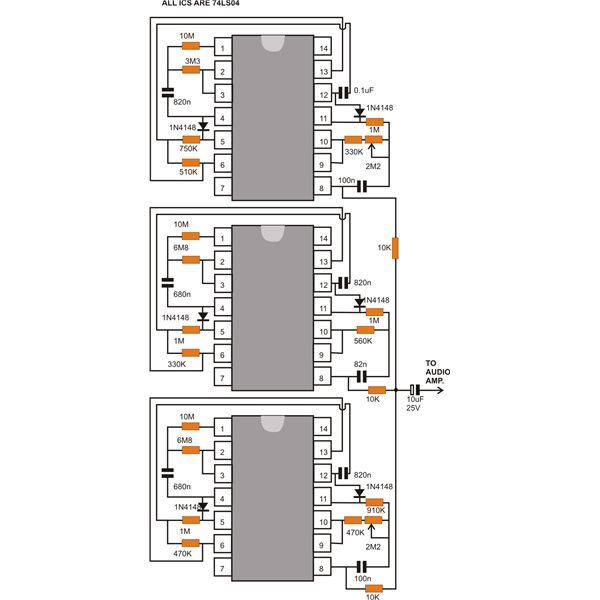
This document discusses a compact machine gun sound effect generator circuit. Once constructed, it can be integrated with any audio amplifier to create a realistic war-like simulation. This small hobby project is suitable for all electronics enthusiasts and generates...
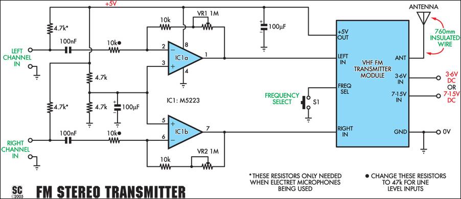
This stereo FM wireless microphone provides a high-quality audio link. Testing demonstrated a reliable performance at distances exceeding 50 meters. While not the first wireless microphone produced, this model stands out due to its stereo capabilities, delivering surprisingly good...
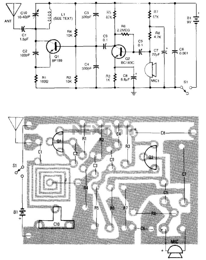
A simple FM wireless microphone utilizes a single BC183C transistor as an audio amplifier, with the option to substitute it with a 2N3565. The transistor Q1 functions as an oscillator that is frequency-modulated by the signal from Q1. Other...
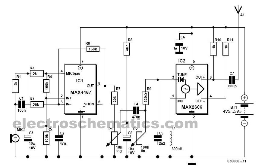
This simple FM wireless microphone transmitter can transmit speech over a short range. It can be used as a simple cordless microphone. The circuit uses two. The FM wireless microphone transmitter is designed for short-range audio transmission, making it suitable...
In its simplest form, a voice-over unit is just a microphone and change-over switch feeding an amplifier, the output from the microphone having priority over the amplifiers audio signal when the "push-to-talk" switch is pressed. In this circuit, a...
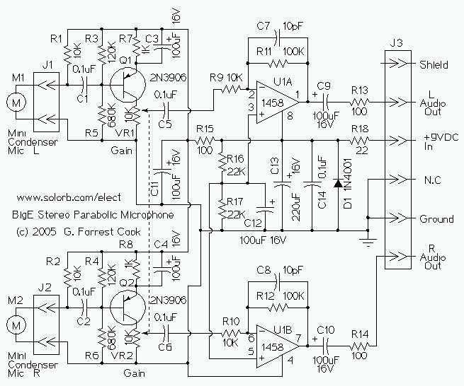
This device is a stereo amplifier for a high sensitivity stereo parabolic microphone. It can be used for listening to distant sounds. The Big-E can be used with headphones or as an audio source for a stereo tape recorder...