
Wireless Fm Microphone

The FM wireless microphone circuit primarily consists of a single transistor amplifier, which serves both as an audio amplifier and an oscillator. The BC183C transistor, known for its high gain and low noise characteristics, is ideal for capturing audio signals and amplifying them for transmission. The circuit operates by modulating the frequency of the carrier wave generated by the oscillator with the audio signal, allowing for wireless transmission of sound.
In this configuration, the Q1 transistor is responsible for generating the RF signal. The audio input, typically from a microphone, is fed into the base of the transistor, which modulates the oscillation frequency in accordance with the audio waveform. The output of the transistor is then transmitted through an antenna, which radiates the modulated signal into the surrounding environment.
When considering substitution of the BC183C with a 2N3565, it is important to analyze the specifications of the replacement transistor. The 2N3565, while capable of functioning in this circuit, may exhibit different gain characteristics or frequency response, which could affect the quality of the audio transmission. Therefore, thorough testing should be conducted to ensure the modulation characteristics remain within acceptable limits.
Additionally, the circuit may incorporate passive components such as resistors and capacitors to stabilize the operation of the transistor and filter the audio signal. The design should also account for power supply considerations, ensuring that the transistor operates within its rated voltage and current specifications to avoid thermal runaway or signal distortion.
In summary, the FM wireless microphone circuit is a straightforward design that leverages the capabilities of a single transistor for audio amplification and modulation. Proper component selection and testing are critical to achieving optimal performance and ensuring reliable wireless audio transmission. A simple FM wireless microphone uses a single BC183C transistor as an audio amplifier. A 2N3565 can be substituted. Ql is an oscillator that is FM modulated by the signal from Ql. Other transistors can be substituted, but the modulation characteristics should be checked.
Related Circuits
Amplifier circuit for electret microphones (condenser microphones). It amplifies the audio signals picked up by the electret microphone using a 741 op-amp and a 2N2222 transistor. The amplifier circuit designed for electret microphones utilizes a combination of a 741 operational...
Ethernet is the most widely used networking technology, known for its high reliability, informative media, and ease of expansion and updates. It is commonly utilized in businesses, schools, and various other fields. According to the IEEE802.3 Ethernet specification, the...
This simple design features very low noise levels, approaching the theoretical minimum, high hum rejection, and variable gain controlled by a single rotary potentiometer. It resembles the circuitry used in many professional-grade mixing desks and can serve as the...
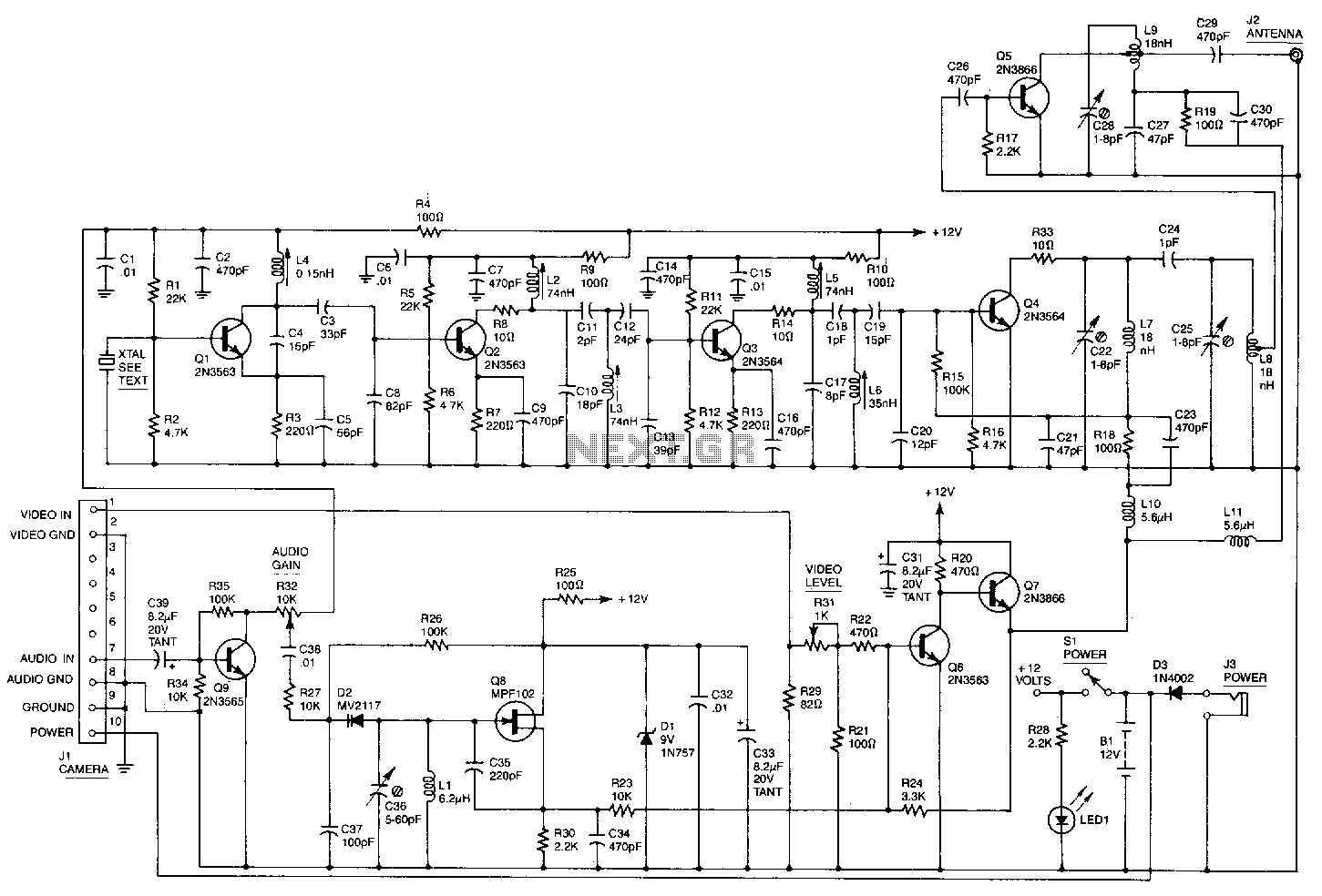
This high-performance video camera link transmits signals from a video camera to a VCR or from a VCR to televisions throughout a home. The initial stage of the RF chain is a crystal-controlled oscillator, Q1, operating at a frequency...
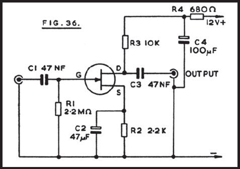
Figure 36 illustrates the circuit of a preamplifier featuring a high impedance input and an output circuit designed for coupling to a main amplifier. This configuration is particularly advantageous for applications such as amplifying the signal from a crystal...
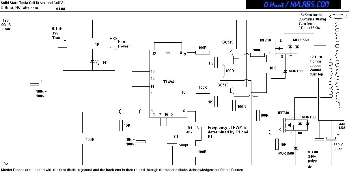
This is a solid-state version of a Tesla coil, replacing the spark gap with MOSFET transistors and utilizing a close-coupled primary coil without capacitors. The method of driving the primary coil varies among designs. After researching various works online,...