
Complete Solid state M-9 Power Amplifier
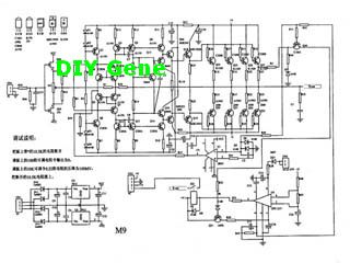
The solid-state M-9 power amplifier circuit is designed to deliver high-quality audio amplification while ensuring the safety of connected loudspeakers through its integrated protection features. The circuit typically consists of several key components, including transistors, resistors, capacitors, and a DC servo system.
The DC servo is a crucial part of the design, functioning to eliminate DC offset at the output. This capability is essential for protecting the loudspeakers from potential damage caused by DC signals. The servo continuously monitors the output voltage and adjusts the biasing of the amplifier’s output stage to maintain a zero-volt level at the loudspeaker terminals. This feedback mechanism ensures that the audio signal remains purely AC, preserving sound quality and preventing distortion.
In addition to the DC servo, the amplifier circuit may include biasing networks that stabilize the operation of the output transistors, ensuring efficient performance across various load conditions. The use of high-quality components in the circuit design contributes to low distortion and high fidelity, making the M-9 amplifier suitable for both professional and home audio applications.
Power supply considerations are also vital; the circuit typically requires a dual power supply configuration to provide the necessary voltage levels for proper amplifier operation. Filtering capacitors are employed to smooth out any ripple in the power supply, ensuring that the amplifier operates with clean and stable power.
Overall, the complete solid-state M-9 power amplifier circuit diagram represents a well-engineered solution for audio amplification, combining performance, reliability, and protection mechanisms to deliver an exceptional listening experience.The following circuit shows about Complete Solid state M-9 Power Amplifier Circuit Diagram. Features: DC servo make a loudspeaker protect circuit, .. 🔗 External reference
Related Circuits
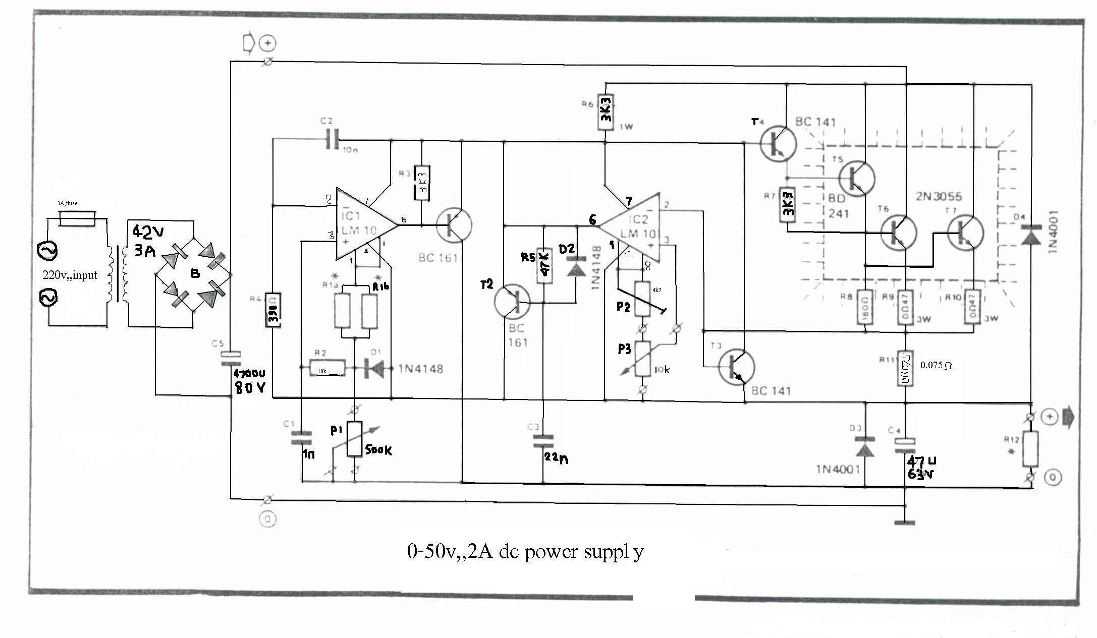
The LM10 integrated circuit (IC) is utilized due to its reference voltage feature, which is beneficial for DC power supply applications. By employing two ICs, it is possible to achieve different output voltages and current levels. The circuit includes...
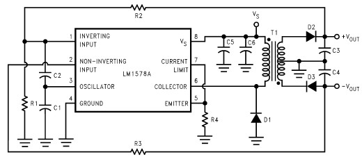
This RS232 power supply circuit diagram is a simple RS-232 line driver power supply that operates from an input voltage as low as 4.2V and delivers an output of ±12V at ±40 mA with an efficiency of better than...
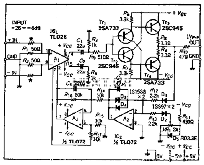
A car circuit is utilized for external voltage-controlled amplification in wideband amplifiers using the TL0216 IC. This design incorporates compression characteristics of 2dB. The input circuit consists of resistors that reduce the input level when it is between -26dB...
300W Subwoofer Power Amplifier. High power amplifiers are not common as projects, as they are inherently challenging to build and often expensive. A minor error during assembly can lead to significant issues. The 300W subwoofer power amplifier is designed to...
The programmable power supply is a component of an integrated test system for guided missiles, designed to provide and test various required stabilized direct current voltage supplies for guided missiles. It features real-time monitoring, overvoltage protection, and automatic overload...
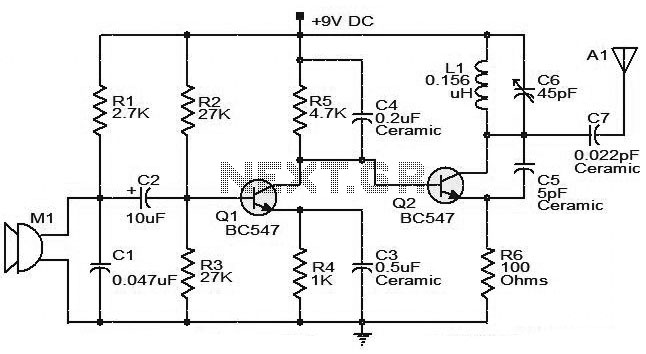
The moderate power FM transmitter circuit employs two transistors. The voice signals picked up by the microphone will be amplified by the transistor. The described FM transmitter circuit utilizes two transistors to facilitate the modulation and amplification of audio signals....