
Microscope stepper controller

The circuit design for the microscope controller integrates an Arduino Uno with a stepper motor shield to control the Phytron ZSS32 stepper motor, which is essential for precise positioning in microscopy applications. The stepper motor is driven by four SN754410 integrated circuits (ICs) connected in parallel to ensure sufficient current supply, as each motor phase requires 1.2A, and the SN754410 is limited to 1A. This configuration allows for a total current capacity of 4A, meeting the motor's requirements without overheating the driver.
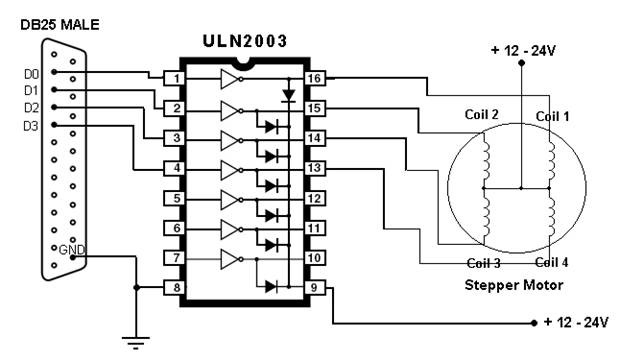
In the schematic, the Arduino is programmed using the Stepper library, which simplifies the control of the motor's movement. The motor is configured with 200 steps per revolution, and the control pins are assigned to digital pins 6, 7, 8, and 9 on the Arduino. The controller also incorporates limit switches connected to digital pins 2 and 3, which prevent the motor from exceeding its operational limits, ensuring that the stage does not move beyond its physical boundaries.
The software implementation involves reading the position of a joystick connected to analog pin A0. This joystick input is utilized to determine the desired position of the microscope stage. The speed of the stepper motor is dynamically adjusted based on the joystick's offset from its center position, allowing for smooth and responsive control. If the joystick is within a certain range of the center value, the motor is disabled to allow for manual adjustments without resistance from the motors.
Additional features include a dimmable LED ring light powered through the USB port of a connected PC, providing effective illumination for the sample without the high costs associated with commercial alternatives. The overall design is modular, allowing for easy integration with existing laboratory equipment, such as mass spectrometers, and is adaptable for various microscopy applications. The entire system emphasizes precision, control, and flexibility, making it suitable for advanced research in microscopy.Built for Birkbeck, the microscope controller is a open source stepper motor driver. It uses an Arduino Uno, and arduino stepper motor shield to drive a Phytron ZSS32. 200 1. 2A 3V stepper motor. To move the sample port, we use an inverted Marzhauser microscope stage, controlled by an Arduino Uno. The Arduino drives four SN754410 quadruple half h d rivers (connected in parallel). The Phytron ZSS33 stepper motors draw 1. 2 A per phase (i. e 2. 4 A) but the SN754410 is limited to 1A, hence four in parallel). The schematic below shows the final circuit, which controls one of the axes. The schematic shows only one SN754410 IC. otherwise it looks messy. I think all the part numbers and connections are correct - check before building! /* * COD (CO2Driver) */ #include
step(1); sensorVal1=analogRead(sensor1); stepper1. setSpeed(spd1); } } //Axis 1 +ve direction - stop moving if limits exceeded int LIM4 = digitalRead(2); // read the input pin if (LIM4 != 0){ if (sensorVal1 >= (defaultval1+20) { stepper1. step(-1); sensorVal1=analogRead(sensor1); stepper1. setSpeed(spd1); } } //When the joystick is at 0, don`t draw current. //This allows motors to be turned manually. if (sensorVal1 < (defaultval1+20) && (sensorVal1 >(defaultval1-20) { digitalWrite(6, LOW); digitalWrite(7, LOW); digitalWrite(8, LOW); digitalWrite(9, LOW); } } Built at the Open University, FLUMP (Fibre Laser Unit on a Mobile Platform) is a SPI 25 W 1090 nm infrared laser mounted in a 19" mobile rack (enabling it to be used on any mass spectrometer).
The 1090nm infrared beam is delivered via a fibre optic cable into a Leitz microscope, where it is directed to the objective, and focussed onto the sample chamber. I wrote the software to control the laser, which can operate in CW mode or a psuedo-pulse mode, with a power range of 5 mW to 24.
7 W, depending on which beam splitter is in place. Individual pulses of >50 ms are possible, which allow infrared spot dating. I also built the dimmable LED ringlight, powered through the USB port of the PC, orders of magnitude cheaper than the commercial versions! I designed and constructed most aspects of this laser, inculding the electronic control for the stepper motors on the XYZ stage, the enclosed beam delivery system, laser shielding, and Zinc Selenide windowed laser port.
Also built at the OU, DiLBeRT (DIode Laser BEnch on a Rolling Trolley) is a SPI G3 series 20W 1062 nm laser which fires through a modified defunct New Wave 213 nm laser. As with the other lasers, this is also mobile. Unlike Flump, this laser is hardware controlled; I put together the electronic control boards which communicate with the SPI hardware, modified the New Wave laser (removing the 213nm optics and installing 1062nm optics), and put
🔗 External reference
Related Circuits
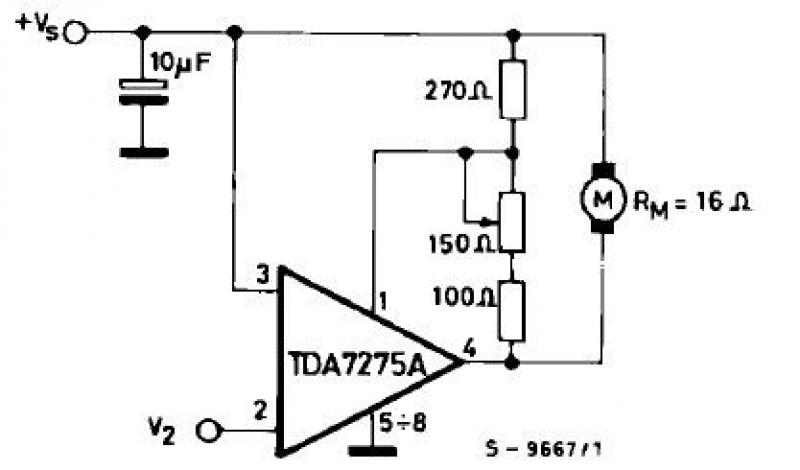
The TDA7275A linear integrated circuit, housed in a minidip plastic package, can be utilized to design a straightforward speed regulator electronic project suitable for regulating the speed of small DC motors. The TDA7275A DC speed controller project is specifically...
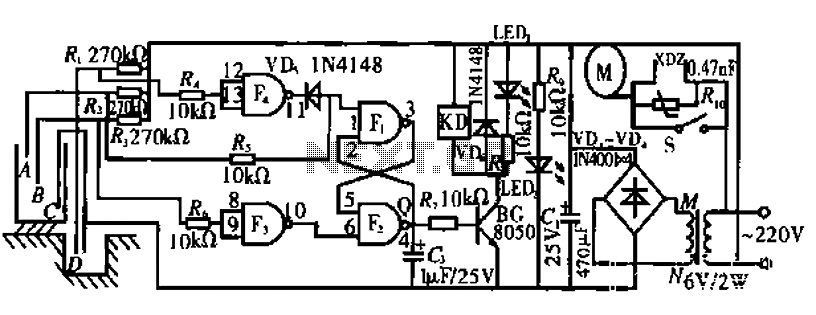
The circuit operates by monitoring the water level in a tank. When the water level falls below a specified point (F), the RS flip-flop (F2) is activated, producing a high Q output that energizes a relay to start the...
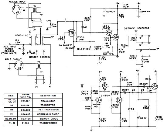
SHURE is an American corporation that manufactures consumer and professional audio electronics, including microphones, phonograph cartridges, and discussion systems. SHURE Incorporated is a well-established entity in the audio electronics industry, recognized for its innovative design and high-quality products. The company...
Instructions for constructing and utilizing a basic PIC programmer using readily available and inexpensive components. The total cost for building the programmer is under $1.50. The simple PIC programmer is designed to facilitate the programming of PIC microcontrollers, which are...
This article outlines the process of connecting a stepper motor to a computer's parallel port and writing code to control it using the scroll wheel of a mouse. For those unfamiliar with stepper motors, this project offers an engaging...

The board can now be tested. Set the DIP switch to Switch1 ON, Switch2 OFF (15-second delay), Switch3 ON, and Switch4 OFF (4 rings to activate half for switching ON). To switch ON relay 1 (connected to RB0 of...
Warning: include(partials/cookie-banner.php): Failed to open stream: Permission denied in /var/www/html/nextgr/view-circuit.php on line 713
Warning: include(): Failed opening 'partials/cookie-banner.php' for inclusion (include_path='.:/usr/share/php') in /var/www/html/nextgr/view-circuit.php on line 713