
What is Microcontroller / PIC programer
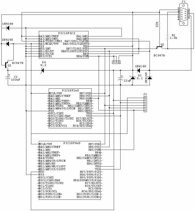
The simple PIC programmer is designed to facilitate the programming of PIC microcontrollers, which are widely used in various electronic applications. The circuit typically requires a minimal number of components, making it an economical choice for hobbyists and engineers alike.
Key components of the programmer include a USB interface for power and communication, a microcontroller socket for the target PIC device, and essential passive components such as resistors and capacitors. The programmer may also utilize a standard 16-pin ICSP (In-Circuit Serial Programming) connector, which allows for easy connection to the microcontroller.
The circuit operates by sending programming signals from a computer via the USB port to the PIC microcontroller. The programmer typically employs a simple transistor-based level shifter to ensure that the voltage levels are compatible between the USB interface and the PIC microcontroller, which may operate at different voltage levels, such as 5V or 3.3V.
For assembly, a printed circuit board (PCB) or a breadboard can be used to mount the components. The connections should be made according to a schematic diagram, ensuring that each component is placed correctly to avoid any potential damage to the microcontroller. Once assembled, the programmer can be connected to a computer running compatible programming software, allowing users to upload code to the PIC microcontroller.
This low-cost solution is ideal for educational purposes, prototyping, and hobby projects, offering a practical way to engage with microcontroller programming without significant investment. Proper attention to detail during assembly and testing will ensure the reliability and effectiveness of the PIC programmer.How to build and use simple PIC programmer with very easy to find and extremely low cost parts. Total cost to build programmer is less than 1.5USD.. 🔗 External reference
Related Circuits
A typical electronic volume control circuit is commonly used in stereo audio devices connected through a computer (CPU). The circuit adjusts the volume of stereo signals via input and output pins. Control signals are sent to the CPU (including...
A matrix keypad is a highly useful and user-friendly component in the design of applications such as calculators and telephones. It consists of push-button switches arranged in rows and columns. For instance, interfacing a 4x4 (16 keys) matrix keypad...
National Instruments Multisim now features microcontroller unit co-simulation capabilities, enabling the inclusion of a microcontroller, programmed in assembly or C code, within SPICE-modeled circuits. The MCU functionality in Multisim allows students, educators, and professional users to program MCUs in...
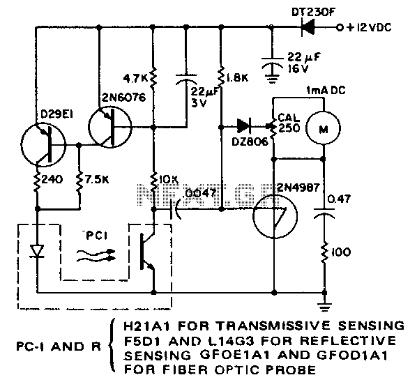
The purpose of this simple circuit is to enable remote, non-contact measurement of the speed of rotating objects. The circuit exhibits high linearity and accuracy, typically constrained by the milliammeter utilized and the initial calibration process. It is configured...
Turning electrical devices ON or OFF using a remote control is a well-established concept, with numerous devices available that perform this function effectively. To create such a device, it is necessary to construct a receiver and a transmitter, as...
The objective of this project is to control the speed of a DC motor. The primary benefit of utilizing a DC motor is the ability to modify the Speed-Torque relationship to nearly any desired form. To facilitate speed control,...
Warning: include(partials/cookie-banner.php): Failed to open stream: Permission denied in /var/www/html/nextgr/view-circuit.php on line 713
Warning: include(): Failed opening 'partials/cookie-banner.php' for inclusion (include_path='.:/usr/share/php') in /var/www/html/nextgr/view-circuit.php on line 713