
MIDI Drum Machine

This schematic illustrates a simplified analog input circuit designed for peak detection and retention, specifically tailored for applications such as electronic drum pads. The core functionality is achieved through a track-and-hold mechanism, which captures the peak voltage of an incoming waveform generated by the pad's transducer.
In operation, when the drummer strikes the pad, the input waveform can reach its peak instantaneously. At this moment, a capacitor within the circuit is charged to the peak voltage level. This peak voltage is crucial as it represents the highest amplitude of the strike, which needs to be recorded for further processing. The circuit employs a single Analog-to-Digital Converter (ADC0804), which converts the analog voltage to an 8-bit digital code. However, due to the conversion time required by the ADC, the track-and-hold circuit ensures that the peak voltage is preserved until the ADC is ready to process it.
The schematic includes two CD4051 8:1 analog multiplexer (MUX) chips, which facilitate the selection of one of eight input signals to be routed to the ADC. The switch labeled "Read" is used to connect the selected input to the ADC for conversion. Once the ADC completes its conversion cycle, a control signal from the central processing unit (CPU) activates the "Clear" switch momentarily. This action resets the track-and-hold circuit, preparing it for the next peak detection.
The resulting waveforms depicted in the schematic show the relationship between the raw input from the transducer and the output signal that is captured by the ADC. The lower waveform represents the unprocessed input, while the upper waveform illustrates the held peak voltage, demonstrating the effectiveness of the track-and-hold circuit in preserving transient signals for accurate digital representation.Simplified Analog Input Schematic This schematic represents the input circuitry for a single input. This circuit is a track and hold. The idea is that the input waveform may reach a peak at any instant as the drummer strikes the pad. When that occurs, the capacitor is charged to the peak input voltage. There is only one A/D converter (ADC0804, see the Main CPU section schematic), and it takes time for it to convert an input voltage to a 8-bit code. No matter when the drummer strikes the pad, the capacitor will "remember" the peak input voltage, so that it can be read later as the A/D convert cycles through the 8 inputs.
This plot shows the track and hold cirucit in action. The lower waveform is the raw input from the pad`s transducer, and the upper waveform is the output which will be read by the A/D converter at some later time. The two switches shown are actually CD4051 8:1 analog MUX chips (see the Complete Analog Schematic. The one labeled Read connects one of the 8 inputs to the A/D converter. After the A/D converter is finished, the CPU briefly closes the Clear switch to dis 🔗 External reference
Related Circuits
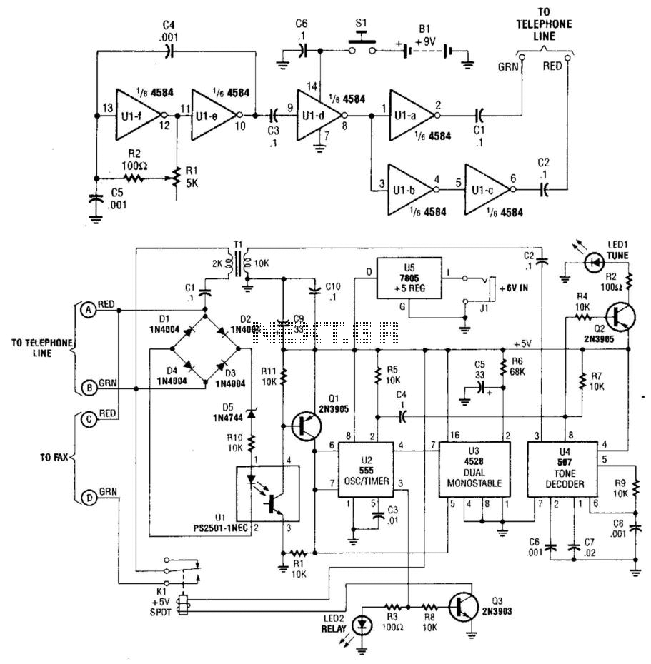
This system uses a transmitter operating at approximately 100 kHz to control a remote receiver. A line splitter can connect the transmitter to the active telephone line. The transmitter is a CMOS oscillator equipped with output buffer stages to...
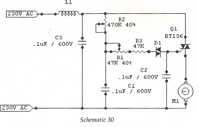
The motor speed control for stitching machines utilizes a series of carbon buttons housed within an enclosure, which are activated by a foot pedal. As the pressure on the foot pedal increases, the motor speed is adjusted accordingly. The motor...
These circuits allow an ON-ON type DPDT toggle switch to control a twin coil switch machine motor. The handle of the switch can then be used to indicate the route selected. The circuits are also able to control LEDs...
The widespread application of Surface Mount Technology (SMT) in products such as computers, network communications, consumer electronics, and automotive electronics has led to increasingly complex, high-precision, and multifunctional electronic assemblies. Accurate testing techniques can enhance manufacturing efficiency and ensure...
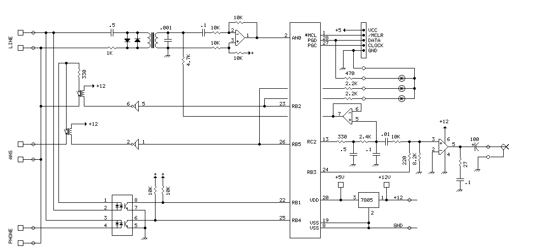
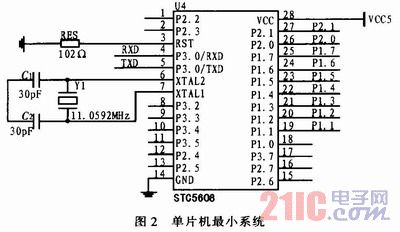
The PIC16F870 chosen for this project has several analog channels. One of these is used to capture the DTMF tones and decode the digits. The actual phone connections are made using a 'hacked' 5 line expander from Radio Shack....
Instructions for constructing a MIDI interface that connects a Sound Blaster (SB), Sound Blaster Pro (SB Pro), or Sound Blaster 16 (SB16) sound card joystick port to a MIDI-capable musical instrument. To build a MIDI interface for connecting a Sound...