
Remote-Controlled Telephone/Fax Machine Switch
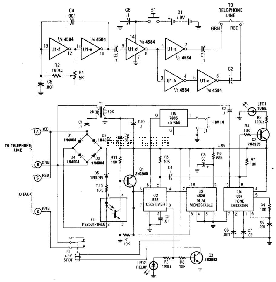
This electronic system is designed to facilitate remote control of a fax machine via a telephone line using a 100 kHz transmitter and a corresponding receiver. The transmitter employs a CMOS oscillator, which is an efficient and stable component for generating the desired frequency. The output buffer stages are crucial for interfacing with the telephone line, ensuring that the signal strength is adequate for reliable operation.
The use of a line splitter is a practical solution for connecting the transmitter to the telephone line without disrupting existing services. This allows the system to function seamlessly alongside typical telephone operations. The receiver monitors the line voltage to detect an off-hook condition, which indicates that the telephone has been lifted. This is a critical feature, as it allows the system to respond appropriately to user actions.
The optocoupler (U1) serves as an isolation component, ensuring that the control logic is protected from high voltage spikes present on the telephone line. When the line voltage drops, the LED in the optocoupler turns off, signaling timer U2 to start its operation. Timer U2 is configured in a latching mode, which is essential for maintaining the control state once activated. It provides a robust mechanism to ensure that once the fax machine is connected, it remains connected until the system is deliberately reset.
The tone decoder (U4) plays a vital role in identifying the specific 100 kHz signal from the transmitter. Upon detection, it outputs a low signal to illuminate LED1, which serves a dual purpose: providing visual feedback to the user and assisting in frequency calibration of the transmitter. This feedback mechanism is important for ensuring that the system operates within the designed parameters.
Relay K1, controlled by transistor Q3, is responsible for switching the fax machine onto the telephone line. The design includes a precautionary measure with U3, which filters out transient signals that could inadvertently trigger the system. This feature enhances the reliability and stability of the operation, ensuring that the fax machine is only connected when intended.
In summary, this system integrates various electronic components to create a reliable and efficient method for controlling a fax machine remotely via a telephone line. The design emphasizes stability, user feedback, and protection against transients, making it suitable for practical applications in environments where telephone line control is necessary. This system uses a transmitter at around 100 kHz (see Fig. 86-3(a)) to control a remote rece iver. A line splitter can be used to connect the transmitter to the telephone line in use. The transmitter is a CMOS oscillator and has output buffer stages to drive the telephone line. When the receiver (Fig. 86-3(b)) detects the off-hook condition (the line voltage drops from about 48 V to less than 10 V). Optocoupler U1 has the LED extinguished. This enables timer U2. When the transmitter is activated, tone decoder U4 detects the 100-kHz signal and outputs a low signal, which lights indicator LED1. LED1 is also used to set the transmitter frequency. Also, U2 is triggered. U2 is configured for the latching condition. U2 feeds the base of Q3, turns it on and energizes relay Kl, which switches in the fax machine to the telephone line.
U3 prevents U2 from being accidentally triggered by transients on the telephone line. When the phone is lifted off-hook and it resets U2 after about one or two seconds of delay, transients are allowed to subside before U2 is reset, and it waits for a negative pulse on pin 2 to turn on. When U2 turns on, Q3 is biased on, which activates change-over relay K1. 🔗 External reference
Related Circuits
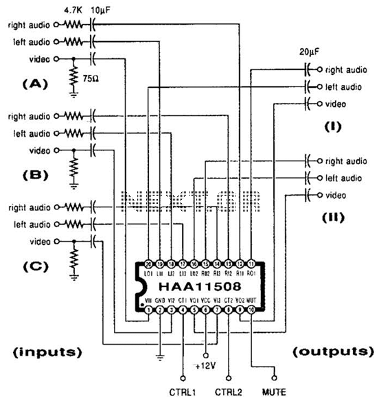
This channel selector selects video and stereo audio from any one of three different sources. The circuit should be constructed on a PC board with plenty of ground plane to minimize noise. The channel selector circuit is designed to facilitate...
The timing circuit utilizes an electronic switch composed of F1, F2, and VT1 to reduce quiescent current to approximately 1 to 2 A with the 555 timer. Upon initial power-up, the voltage across capacitor C2 cannot instantly change, causing...
Any button from any remote control can be used to operate this universal switch. The button needs to be pressed for two seconds (determined by R3 and C2) before the relay activates. Once activated, the circuit remains latched in...
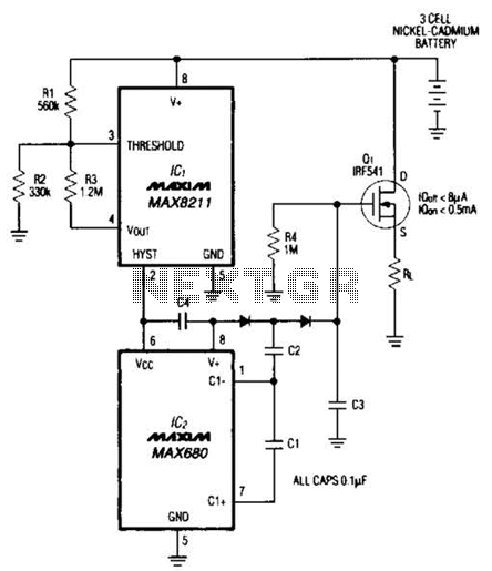
Deep discharge can damage a rechargeable battery. By disconnecting the battery from its load, this circuit halts battery discharge at a predetermined level of declining terminal voltage. Transistor Q1 acts as the switch. The overall circuit draws about 500µA...
This circuit functions as a camera switch, allowing multiple cameras to be connected to a single monitor. It can operate in both manual and automatic modes. In automatic mode, the circuit utilizes a 555 astable multivibrator to generate a...
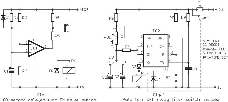
A relay (RL1) is activated with a 100-second delay when a +12V power supply is connected to the circuit. Figure 2 illustrates a relay timer circuit utilizing a 555 timer, featuring two time ranges: 6-60 seconds and 1-10 minutes...
Warning: include(partials/cookie-banner.php): Failed to open stream: Permission denied in /var/www/html/nextgr/view-circuit.php on line 713
Warning: include(): Failed opening 'partials/cookie-banner.php' for inclusion (include_path='.:/usr/share/php') in /var/www/html/nextgr/view-circuit.php on line 713