
Stitching Machine Motor Speed Control
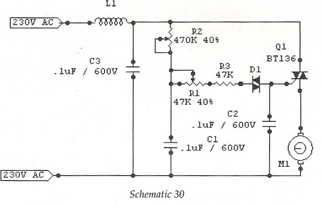
The motor speed control circuit for stitching machines is designed to provide precise control over the operation of the motor, allowing for varying stitching speeds based on user input. The system typically includes a foot pedal interface, which incorporates a variable resistor or potentiometer to detect the pressure applied by the operator.
When the foot pedal is pressed, the resistance changes, sending a corresponding voltage signal to the motor controller. This controller interprets the voltage level and adjusts the power supplied to the motor, thereby controlling its speed. The enclosure containing the carbon buttons serves as a protective housing, ensuring durability and reliability in a workshop environment.
Additional components may include a microcontroller for enhanced functionality, enabling features such as programmable speed settings and feedback mechanisms. Safety features such as overcurrent protection and thermal shutdown may also be integrated into the circuit to prevent damage to the motor and associated components.
The overall design emphasizes efficiency and user-friendliness, allowing operators to achieve optimal stitching results with minimal effort. Proper attention to the selection of materials and components is essential to ensure longevity and consistent performance in industrial applications.Stitching Machine Motor Speed Control, Motor operated stitching machines have a series of carbon buttons in an enclosure operated by foot pedal. As the pressure on the foot pedal is increase.. 🔗 External reference
Related Circuits
The circuit is designed to operate with an external power supply, which is why it does not include a transformer, rectifier, or filter capacitors in the schematic. However, these components can be added if desired. To utilize the circuit,...

This project focuses on the design and development of a theft control system for automobiles, aimed at preventing and controlling vehicle theft. The system utilizes an embedded design based on GSM and GPS technology. It is installed within the...
Introduction In this post, the latest application developed from the modular remote control project initiated in the April issue is presented. The modular remote control system is designed to enhance user interaction with various electronic devices through a flexible and...
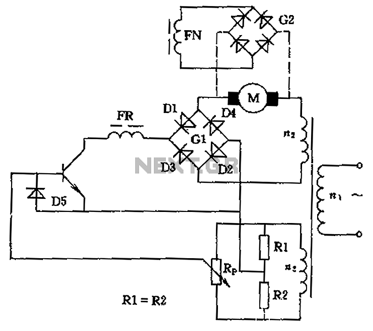
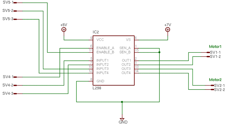
The circuit is designed to control the speed and direction of low-power DC motors, including series and shunt motors. It utilizes a rectifier bridge (G1) connected in series with the motor and linked to the secondary winding (n2) of...
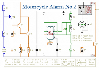
Any number of normally-open switches may be utilized. Install "tilt" switches that close when the steering is moved or when the bike is lifted off its side-stand or pushed forward off its centre-stand. Employ micro-switches to secure removable panels...
The basic stamp cannot directly power motors due to its maximum current output of only 20mA, while motors typically require around an amp or more, with even higher current spikes. To address this limitation, a circuit will be implemented...