
Simple Day/Night switch (40106B)
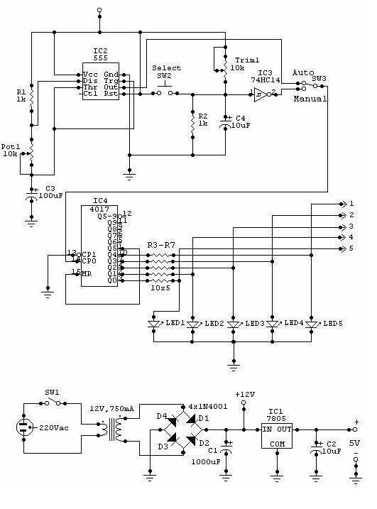
The described circuit functions as an automatic day/night switch, utilizing a photoresistor or light-dependent resistor (LDR) in conjunction with a potentiometer (POT1) to control the switching mechanism based on ambient light levels. The circuit typically includes a comparator, which compares the voltage across the LDR with a reference voltage set by the potentiometer.
When the ambient light level falls below the threshold set by POT1, the comparator output changes state, triggering a relay or a transistor to switch on connected loads, such as outdoor lights or other devices. Conversely, as the light level rises above the threshold, the output state changes again, turning off the load.
The circuit may also incorporate additional components such as capacitors for noise filtering and resistors to limit current through the LDR and ensure stable operation. The design should ensure that the LDR is shielded from direct light sources to prevent false triggering during transient conditions.
For practical implementation, it is essential to choose the appropriate values for the resistors and the potentiometer to achieve the desired sensitivity and response time. Testing under various lighting conditions will help fine-tune the circuit for optimal performance. This circuit is suitable for applications in outdoor lighting systems, garden lights, or any scenario where automatic control based on light levels is beneficial.This is a simple circuit that does the day/night switchings you have in mind. POT1 is used to set the light level at which the circuit switches from enable to disable. 🔗 External reference
Related Circuits

A, B, and C are used for a high-power split-phase system. The A + B' C' arrangement serves as a phase line for a range generator. The A-A' indole path string includes two 220V / 15W bulbs, which are...
This is a clap switch designed to avoid false triggering. To activate or deactivate any appliance, a user must clap twice. The circuit changes its output state only when two claps are detected within a specified time frame of...
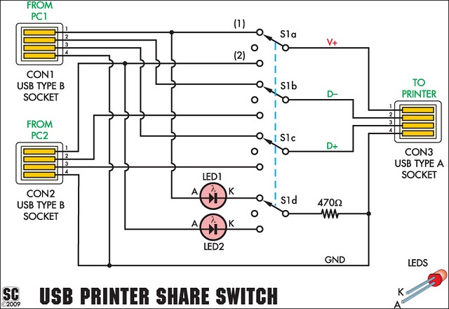
This simple device enables two computers to share a single USB printer or other USB devices, such as an external flash drive, memory card reader, or scanner. A rotary switch is used to select the PC that will be connected...
The multimeter should be set to the lowest DC volts range for maximum sensitivity, typically 200mV DC for most meters. The circuit operates effectively at VHF frequencies, approximately 100MHz, yielding satisfactory results. The inductor L1 consists of 7 turns...

This is a simple XTal tester circuit. T1 and XTal have formed an oscillator. C1 and C2 are voltage divider for oscillator. if the XTal is safe, the oscillator will work well and its output voltage will be rectified...
This circuit can be utilized for multiple cameras with a single monitor. The operation can be manual or automatic. In automatic mode, the switch... This circuit is designed to enable the connection of multiple cameras to a single monitor, allowing...