
mini audio analyzer

The circuit design for this acoustic signal analyzer includes several key components: a microphone, an analog-to-digital converter (ADC), a microcontroller, and an LED driver circuit. The microphone captures the acoustic signal and converts it into an electrical signal. This signal is then processed by the ADC, which digitizes the analog signal for further analysis.
The microcontroller plays a crucial role in interpreting the digital signal. It analyzes the frequency and width of the incoming signal using digital signal processing (DSP) algorithms. The width of the signal is assessed by measuring the duration of the signal peaks, while the frequency is determined by calculating the intervals between the peaks.
To control the LED output, the microcontroller uses a PWM (Pulse Width Modulation) technique. The brightness of the LED is varied according to the calculated width of the signal; a wider signal results in a brighter LED. The color of the LED is controlled by varying the current through different colored LEDs or using an RGB LED, where the microcontroller adjusts the intensity of each color channel based on the detected frequency.
In summary, this acoustic signal analyzer provides a visual representation of the signal characteristics through LED brightness and color, effectively allowing users to interpret the frequency and width of acoustic signals in real-time.This analyst is, a sensitive instrument, in the frequency changes and width of a acoustic signal. Thus the brightness of LED that turns on each moment of is proportional signal width, while the colour of proportionally frequency.. 🔗 External reference
Related Circuits
This circuit is designed to drive a low-power speaker using a sound effects module or a noise generator. It can also be utilized to create amplified speakers for computer use. The circuit amplifies the input signal by a factor...
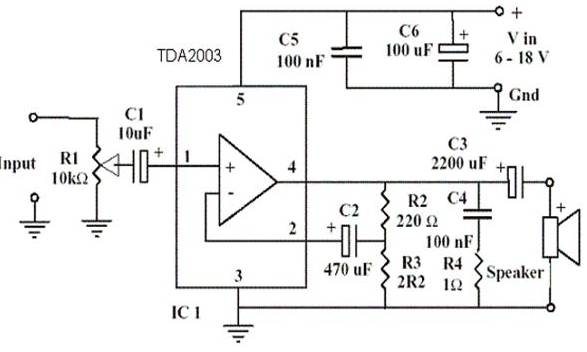
An amplifier device accepts a varying input signal and produces an output signal that varies in the same manner as the input but with a larger amplitude. The input signal can be a current, voltage, mechanical motion, or any...
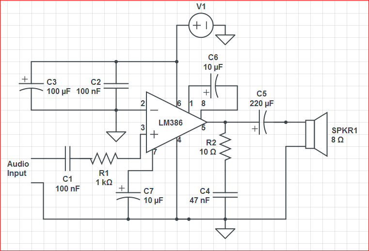
Initially, the circuit was connected to a 9V battery, which registered approximately 8.3 volts on a multimeter, within the operating voltage range for the LM386 as indicated in its datasheet. The output was characterized by significant noise, including crackling...
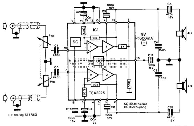
Using a Thomson TEA2025, this stereo amplifier delivers 1 W per channel into a 4-ohm load with a 9-V supply. The input sensitivity is 25 mV peak-to-peak for full output. It is important to ensure that pins 4, 5,...
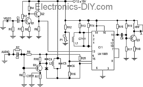
This TV transmitter transmits audio and video signals from camcorders, DVD players, VHS players, satellite systems, video games, etc., broadcasting them on a channel free from the VHF strip. These signals can be radiated using a common antenna and...
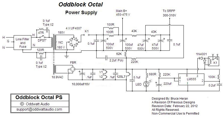
One of the advantages of hosting a hobby website is the opportunity to connect with individuals via email who share similar interests. Since posting Bruce's initial OddWatt project on the site, communication has occurred with numerous DIY hobbyists who...