
Mini Audio Signal Generator
An audio test generator is an essential tool in the field of audio engineering, primarily utilized for troubleshooting and testing audio equipment. This device generates audio signals at various frequencies, which can be used to evaluate the performance of audio circuits and components. The generator typically produces sine, square, or triangle waveforms, allowing technicians to assess frequency response, distortion, and overall signal integrity.
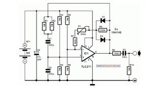
In a typical schematic design for an audio test generator, the circuit may include a waveform generator IC, such as the 555 timer or a dedicated audio oscillator. The output stage often incorporates an operational amplifier to buffer the signal and provide sufficient drive capability for the load. Additional features may include adjustable output levels, frequency selection switches, and LED indicators to display the operational status of the generator.
For practical applications, the audio test generator can be connected to various audio devices, such as mixers, amplifiers, and speakers. By injecting a known signal into these devices, engineers can trace the signal path and identify any issues in the audio chain. This tool is particularly valuable in repair shops and during the development of new audio products, where quick diagnostics can significantly expedite the testing process.
Overall, the audio test generator serves as a fundamental instrument in the audio engineering toolkit, enabling efficient signal tracing and performance evaluation across a wide range of audio equipment.A small audio test generator is very useful for quickly tracing a signal through an audio unit. Its main purpose is speed rather than refinement. A single.. 🔗 External reference
Related Circuits
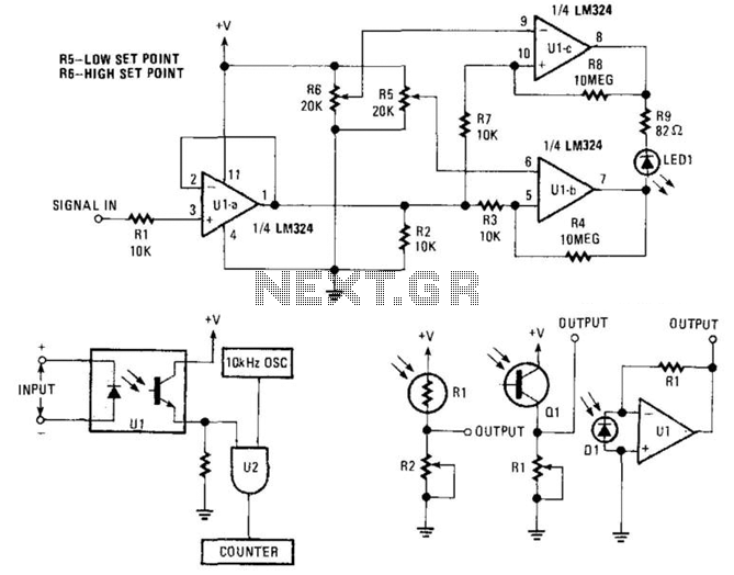
This window generator utilizes a single LM324 operational amplifier and includes two adjustable set points. When the two comparators formed by U1B go high, LED1 illuminates. When U1C goes high, the LED turns off. Hysteresis is implemented using 10...
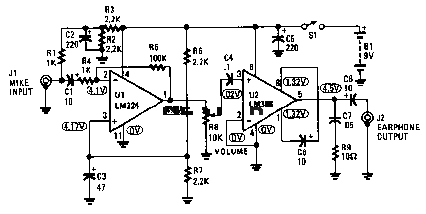
The amplifier captures the audio output signal from the TV and amplifies it to drive a set of earphones for private listening. It is constructed using an LM324 quad operational amplifier and an LM386 low-power audio amplifier. The circuit...
The UDA1343TT is a single-chip stereo analog-to-digital converter (ADC) and digital-to-analog converter (DAC) that features basic signal processing capabilities using bitstream conversion techniques. Its low power consumption, compact package size, and low voltage requirements make it highly suitable for...
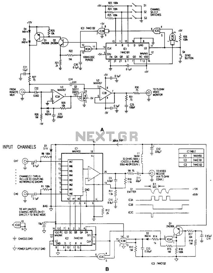
In the video system illustrated in Figures A and R, a single coaxial cable transmits power to a remote location, selects one of eight video channels, and returns the selected signal. This system can choose from several remote surveillance...
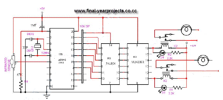
This is a comprehensive electrical project report on an Infrared Remote Control On/Off Switch, submitted to fulfill the requirements for the Bachelor of Engineering degree in Electrical Engineering. The project is designed to control the operation of home appliances...
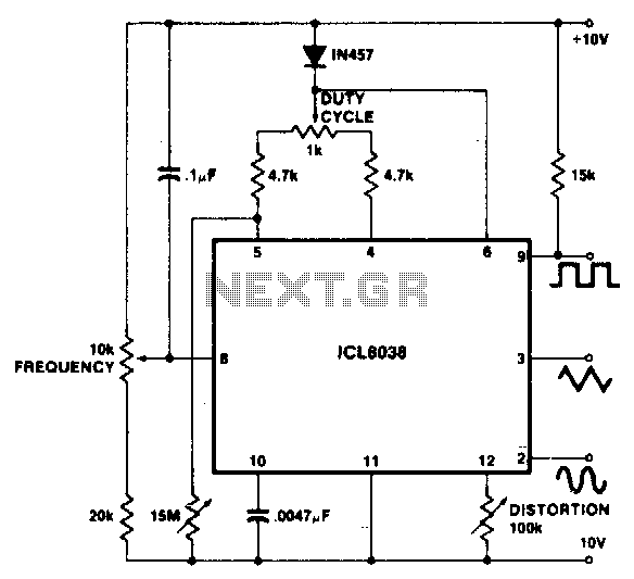
To achieve a 1000:1 sweep range, the voltage across the external resistors Ra and Rb must be reduced to nearly zero. This necessitates that the maximum voltage on control pin 8 surpasses the voltage at the top of Ra...
Warning: include(partials/cookie-banner.php): Failed to open stream: Permission denied in /var/www/html/nextgr/view-circuit.php on line 713
Warning: include(): Failed opening 'partials/cookie-banner.php' for inclusion (include_path='.:/usr/share/php') in /var/www/html/nextgr/view-circuit.php on line 713