
Mini Class A Audio Amplifier

More: The sound of this amplifier is very good for such a simple design, lively and three-dimensional. No cross-over hardness or other transistor nasties. However, don’t push it too hard for then you will begin to hear harmonic distortion. Singers will sound as if they keep both their hands, like a cup, in front of their mouth. If this happens, reduce the volume (or use speakers with a greater efficiency).
P1: 47k log potentiometer (separate for each channel)
R1: 100k
R2: 12k
R3: 47k
R4: 8k2
R5: 1k5 (optional)
R6: 2k7
R7, R9: 100 Ohm
R8: 560 Ohm
R10: 1 Ohm 3W
(all resistors ½ W unless otherwise indicated)
(R5 and C5 are an optional bass-boost facility)
(these parts can be omitted, I did not use them)
C1, C2: 10µF 63V
(I omitted C1 and I used a MKT cap for C2)
C3: 47µF 25V
C4: 100µF 35V
C5: 150nF 63V MKT or MKP (optional)
C6, C7: 220µF 25V
C8: 1000µF 25V
Q1: BC560C (I used a 2SA970)
Q2, Q3: BD439
Sizable heatsink capable of dissipating 17 Watts continuously
The described minimalist amplifier circuit employs a simple yet effective design philosophy aimed at achieving high-quality audio performance with low component costs. The amplifier is constructed using discrete components, which allows for flexibility in sourcing parts, particularly from surplus or salvaged electronics. The power supply is critical, utilizing a regulated source to ensure stability across the two amplifier channels, with a specified secondary voltage of 60V from the transformer, which is essential for the amplifier's operation.
The use of fast recovery diodes (D1 and D2) such as MUR860 minimizes switching losses, contributing to the overall efficiency of the circuit. The capacitor bypassing strategy, particularly for C7, C10, and C11, enhances the amplifier's frequency response and transient performance by reducing high-frequency noise.
The amplifier's sound quality is noted for its liveliness and three-dimensionality, avoiding common audio pitfalls such as crossover distortion. However, caution is advised when increasing volume levels, as excessive drive can lead to harmonic distortion, which may adversely affect audio clarity. The optional components, such as R5 and C5, allow for custom tuning of bass response, providing additional versatility depending on listener preference and speaker characteristics.
The component selection includes various resistors and capacitors, with specific values indicated for optimal performance. The transistors Q1 (BC560C or alternative 2SA970) and Q2/Q3 (BD439) serve as the primary amplification elements, with the design allowing for straightforward replacement or upgrades as needed.
A heatsink must be employed to dissipate the generated heat effectively, with the specified rating of 17 Watts being crucial for maintaining performance and reliability during extended operation. The overall construction of the circuit emphasizes simplicity and efficiency, making it accessible for hobbyists and audio enthusiasts alike.The philosophy behind this minimalist design has been explained by Flavio Dellepiane on his highly interesting site 1. I have myself written an article about this fleapower amp from Italy in the American magazine AudioXpress 2.
All relevant details are published there. A single channel of the amplifier can be built for only a few Euros, especially if you have a well-stocked junkbox. I used a regulated power supply to feed the two amplifier channels, Q6 is mounted on a heatsink. The power transformer comes from a damaged TEAC amplifier. It has a secondary voltage of 60V with a center tap. D1 and D2 are fast recovery diodes, e.g. MUR860. It is a good idea to bypass C7,C10 and C11 with smaller MKT or MKP capacitors. The sound of this amplifier is very good for such a simple design, lively and threedimensional. No cross-over hardness or other transistor nasties. However, don’t push it too hard for then you will begin to hear harmonic distortion. Singers will sound as if they keep both their hands, like a cup, in front of their mouth. If this happens, reduce the volume (or use speakers with a greater efficiency). P1: 47k log potmeter (separate for each channel) R1: 100k R2: 12k R3: 47k R4: 8k2 R5: 1k5 (optional) R6: 2k7 R7,R9: 100 Ohm R8: 560 Ohm R10: 1 Ohm 3W (all resistors ½ W unless otherwise indicated) (R5 and C5 are an optional bass-boost facility) (these parts can be omitted, I did not use them) C1,C2: 10µF 63V (I omitted C1 and I used a MKT cap for C2) C3: 47µF 25V C4: 100µF 35V C5: 150nF 63V MKT or MKP (optional) C6,C7: 220µF 25V C8: 1000µF 25V Q1: BC560C (I used a 2SA970) Q2,Q3: BD439 Sizable heatsink capable of dissipating 17 Watts continuously 🔗 External reference
Related Circuits
This is a 7-tube, 20-watt amplifier that must be used in conjunction with a preamplifier featuring volume and tone controls. A suitable recommendation is a 6-tube preamplifier. This amplifier utilizes 6BQ5 output tubes and employs a 5U4-G rectifier to...
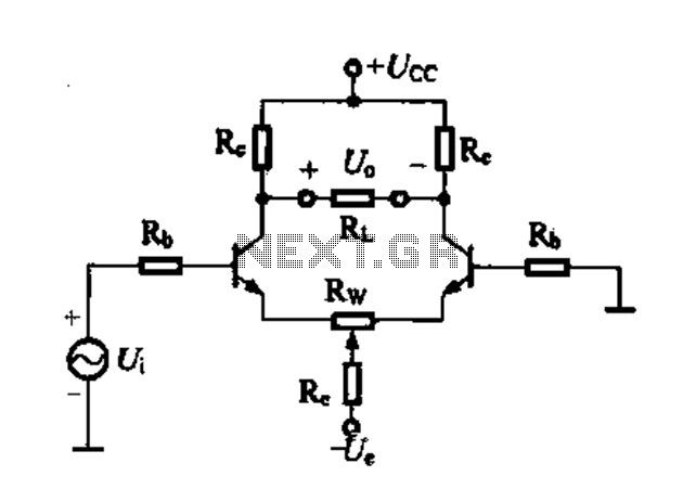
Differential amplifier circuit with four connection methods and characteristics for comparison. The circuit exhibits magnification with a single tube when symmetrical. Additionally, CMRR (Common Mode Rejection Ratio) is adapted from single-ended input to a double-ended output. The differential amplifier is...
This circuit utilizes an EXAR XR2206 to generate sine, square, and triangular waveforms ranging from Hz to 100 kHz. The XR2206 chip (U1) is responsible for waveform generation, with resistor R7 regulating the frequency. Resistors R55 through R58 are...
The following circuit illustrates a Bass and Treble Controller Circuit. This circuit is constructed based on the classic Baxandall tone control circuitry. The Bass and Treble Controller Circuit is designed to adjust the low and high-frequency response of audio signals,...
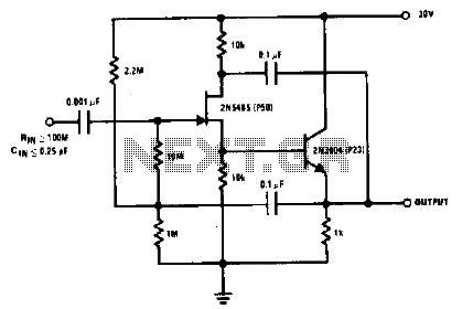
The 2N5485, which has a very low-capacity legacy, is always operated as a source follower with gate bias bootstrap. In this circuit, nothing is left to chance in reducing input capacitance. The 2N5485 is a JFET (Junction Field Effect Transistor)...
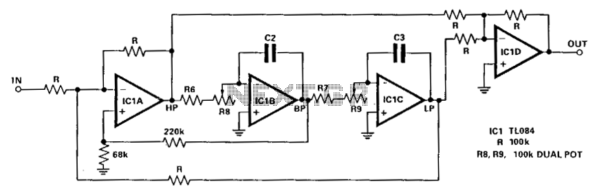
The circuit illustrated here demonstrates that the response at one octave off-tune remains within 10% of the far-out response. The sharpness of the notch can be adjusted by increasing or decreasing the 68-ohm resistor. The linearity tracking of resistors...