
High gain amplifier circuit
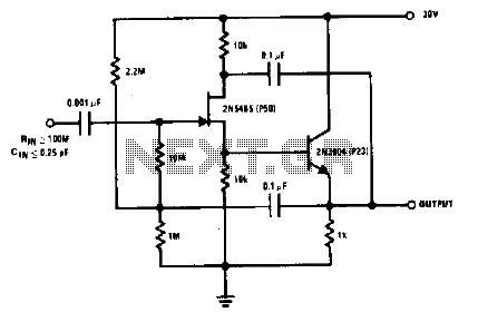
The 2N5485 is a JFET (Junction Field Effect Transistor) known for its low input capacitance, making it suitable for high-frequency applications where signal integrity is crucial. Operating it as a source follower configuration allows for high input impedance and low output impedance, which is beneficial in minimizing signal loss and preserving the integrity of the input signal.
In a typical source follower circuit using the 2N5485, the gate of the transistor is connected to the input signal, while the source is connected to the output. The drain is usually connected to a higher voltage supply. The gate bias bootstrap technique is employed to enhance the linearity and stability of the circuit. This technique involves using a resistor network to create a stable biasing condition at the gate, which helps maintain the transistor's operating point despite variations in temperature or supply voltage.
To further reduce input capacitance, careful attention is given to the layout and component selection within the circuit. This includes minimizing the length of traces connecting the input, gate, and source to reduce parasitic capacitances. Additionally, using high-quality, low-capacitance components can significantly improve the performance of the circuit.
In summary, the 2N5485 source follower circuit, with its gate bias bootstrap configuration, is meticulously designed to minimize input capacitance, ensuring optimal performance in high-frequency applications.The 2N5485, which has a very low-capacity legacy first, is always operated as a source follower with gate bias bootstrap. In this circuit nothing is left to chance in reducing input capacitance. 🔗 External reference
Related Circuits
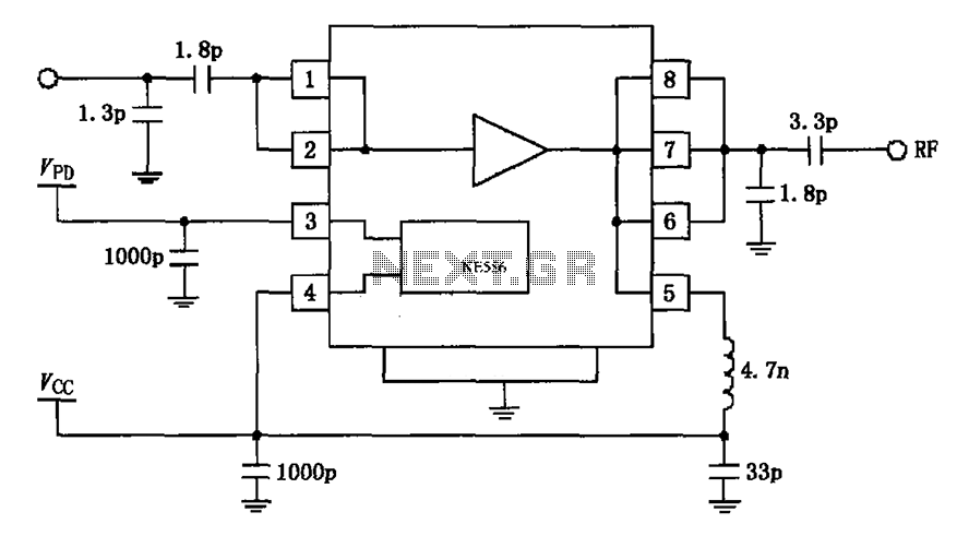
The circuit depicted in the figure is based on the RF2126, a 2450 MHz end-stage linear power amplifier. The radio frequency (RF) signal enters through input pin 1 and is subsequently amplified by the amplifier stages (pins 5, 6,...
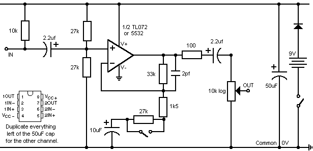
This design addresses the limitations of the microphone preamp in the Sony R91, which clips at low levels, providing only 28mV of headroom for an input that may reach 1800mV, depending on the microphone and volume settings. The design...
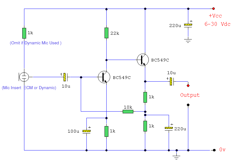
Both transistors should be low noise types. In the original circuit, BC650C was used, which is an ultra-low noise device. These transistors are now hard to find, but BC549C or BC109C are good replacements. The circuit is self-biasing and...
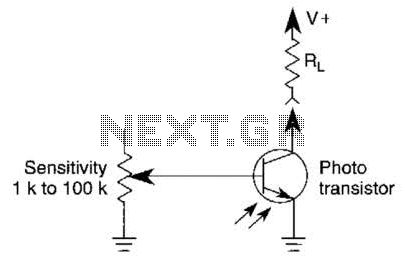
A variable resistor is utilized to adjust the light-level response of a phototransistor. Phototransistors exhibit higher light sensitivity compared to photodiodes; however, they typically demonstrate a lower frequency response. A variable resistor, often referred to as a potentiometer or rheostat,...
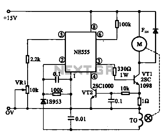
The Miniature DC Motor Speed Control circuit is designed to maintain a steady speed for micro motors, as illustrated in Figure 8-32. The circuit utilizes a voltage feedback mechanism suitable for applications such as tape recording machines that employ...
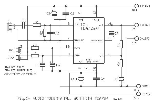
The TDA7294 amplifier module is a monolithic integrated circuit designed for use as an audio class AB amplifier in hi-fi applications. It has a wide voltage range and output current capability, enabling it to supply the highest power into...
Warning: include(partials/cookie-banner.php): Failed to open stream: Permission denied in /var/www/html/nextgr/view-circuit.php on line 713
Warning: include(): Failed opening 'partials/cookie-banner.php' for inclusion (include_path='.:/usr/share/php') in /var/www/html/nextgr/view-circuit.php on line 713