
Mini efficient coil launcher from disposable camera flash

The described coil launcher project utilizes principles of electromagnetism and energy storage to achieve projectile launching. The ferromagnetic projectile is accelerated through the coil by the magnetic field generated when the coil is energized. The timing of the power pulse is critical; it must be precisely controlled to ensure that the projectile is at the optimal position within the coil when the power is turned off. This can be achieved through various methods, including the use of optical sensors that detect the projectile's position.
The design incorporates high-capacity electrolytic capacitors that allow for rapid energy discharge, resulting in high peak currents essential for effective launching. The choice of components, such as the 2N6509 SCRs, is crucial as they must handle significant current loads while providing reliable switching capabilities. The inclusion of a reverse diode serves to protect the capacitors from damaging voltage spikes that can occur in an undamped LCR circuit, ensuring the longevity and reliability of the system.
The coil's construction is also a vital factor in the performance of the launcher. The winding technique, number of turns, and choice of materials all contribute to the efficiency of energy transfer from the coil to the projectile. The use of a glass or plastic barrel minimizes eddy currents, which can detract from the system's efficiency. The overall design requires careful consideration of both electrical and mechanical parameters to achieve a successful and safe projectile launch.
Overall, this project exemplifies the integration of theoretical knowledge and practical application in the field of electromagnetism and energy storage systems, providing a platform for further experimentation and development in magnetic projectile launching technology.This is a fun and non-dangeros project for those people who like to throw projectiles magnetically. It simply works by placing a ferromagnetic projectile at one end of a coil and pulsing some power in it. The trick is to switch off power when the projectile is at the middle of the coil, there are some ways to do it but it isn`t important now.
The second trick is to use a coil as close as possible to projectile to waximize coupling and the third to avoid saturation, that means keeping the current not to high. I`ve been messing with coil launchers for a year. The first model was a straw with some wire wrapped on it and an electrolityc capacitor (200V) pulsed in it.
Lots of sparks and metal flying but was able to shoot a nail accross my room. I started esperimentation wrapping wire on glass and using more litycs charged by mains power, very bulky and disappointing (100J of energy where only able to blast through 2 sheets). After holydays I started more mature experimentation employing SCRs (solid state switching) photoflash electrolytics and optical sensors, and built a bi-coil launcher (2 stages), complicated but poweful ( blasted through a can) but the timing is critical, so transient simulations were a must (and a L-C-R meter).
The next launcher will be mosfet-switched with 3 coils and optical sensors, but i don`t have the funds/parts yet to build such an expensive launcher, but already designed plans and models. For now i decided to build a small funny coil launcher using one scr and coil on glass. Using my LCR meter and multisim simulator i designed it for max efficiency. For first you need some disposable camera flashes, so try to search at your local photo shop. You need 4 of more of them. Desolder the caps and collect them. They have ratings of 330V 120-160uF and can survive pulses up to 300A (each), or even dead shorts (but don`t do it because it is quite a bang).
Paralleling them reduces the ESR (internal resistance) and ESL and highers peak current capability. I used 4 of them and my coil launcher has a pulse current of 400A (about 100A for cap). The more caps, the more energy but more longer pulse, so the additional energy may slow down the projectile instead of fastening it so I would advice to keep them only 4. I trusted the simulations and have almost broken a window with this thing ;-) fortunately the curtains slowed it down.
Concerning the charging circuit, use the largest you got, and try to use more batteries than originally if you want a fast charge. I used a max kodak disposable flash and it works fire with 4 1. 5V batteries (originally it was designed to use one) and doesn`t burn out. The caps where soldered on a small breadboard with parallel tracks made with lots of solder (otherwise the solder will blow).
The coil was made with 200 turns distributed on 10 layers (rembember to insulate eachover) of insulated magnet wire with 1mm diameter on a glass pipe with 6 mm external diameter and 3 mm internal diameter. Also plastic works good as barrel but must be hard, metals must be NON-Ferromagnetic and must have a cut along the barrel lenght (to limit eddy currents).
The resistance is 350 milliohm and inductance is 165 uH (according to my LCR meter) giving a pulse lenght of 1 ms (Multisim simulation) and peak current of 400A, limited by inductance. Using more caps would increase pulse current because the resistance is low and the current is Inductance-limited, so i advice to use only 4 caps (maximum 5).
Concerning the switching i used 2N6509 SCRs (Onsemi) (25A 800V) which have a pulse rating of 300A x 6 ms (450 x 1ms). They are very good cheap and small and requires small signal to drive. A reverse diode was added to the caps because the simulations showed a peak reverse voltage in capacitors (it is an undamped LCR circuit) that could damage them.
This solution limits reverse charging (to -0. 5 V to 1V) and makes the current decay better reducing the 🔗 External reference
Related Circuits
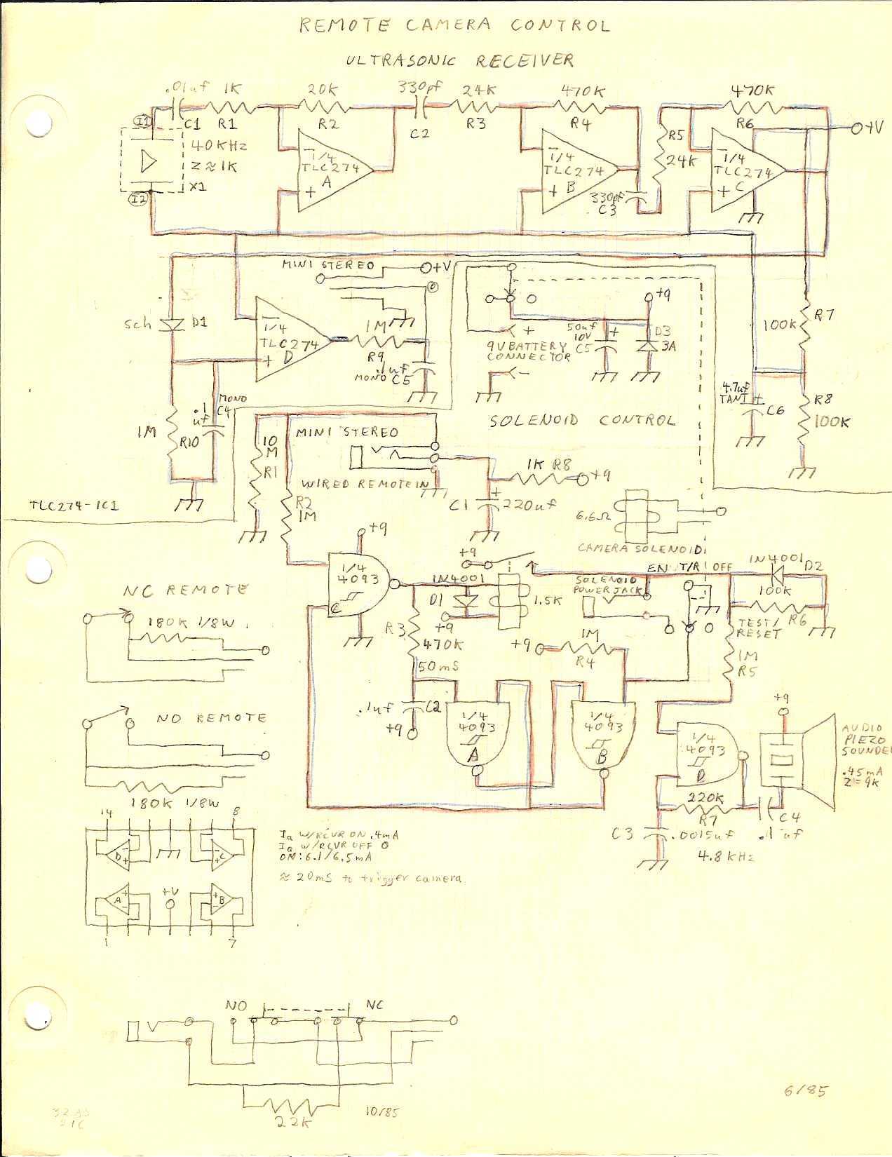
To sense a rocket launch, this clip is simply clipped onto one of the fins of the rocket. The cable is taped or tied to a leg or other part of the launch pad, with the length of cable...
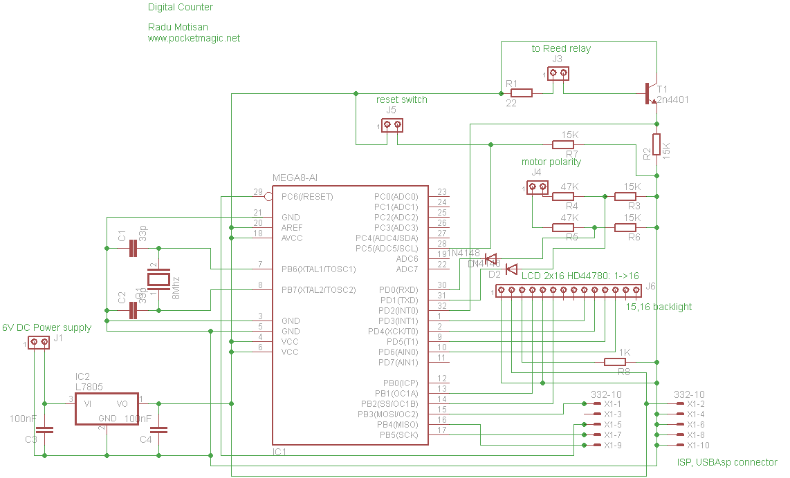
The circuit utilizes an Atmega8-8PU microcontroller configured for 8MHz operation with an external crystal oscillator. It incorporates a Nokia 5110 LCD and a transistor to manage the pulses generated by a reed relay. A 3.3V voltage regulator supplies power...
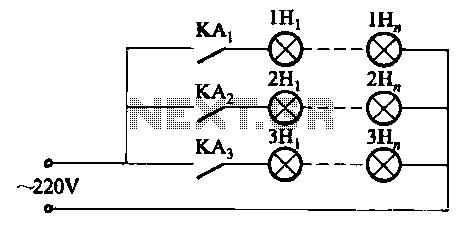
The relay control system utilizes multiple pairs of contacts, allowing for the connection of higher power lamps in parallel. The circuit design is straightforward; by altering the capacitance of the capacitor, different flashing frequencies can be achieved. The described circuit...
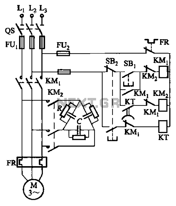
The circuit illustrated in Figure 3-151 consists of capacitor banks arranged in a specific configuration. Figure 3-151 (a) depicts capacitor banks connected in a shaped manner, which is suitable for use with shaped or Y-connected motors. Figure 3-151 (b)...
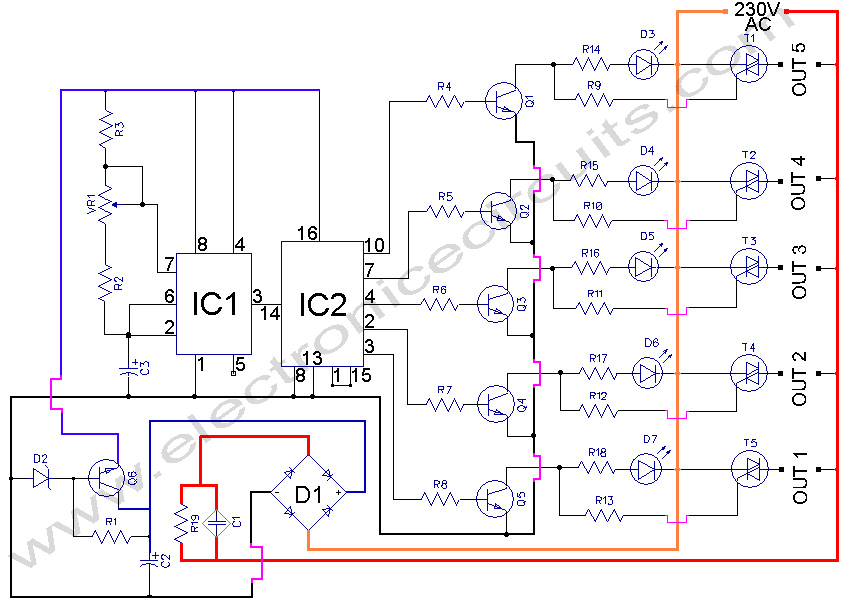
5 WAY AC FLASHER. These types of circuits are commonly used in various ceremonies such as the Wesak festival, Christmas, and weddings. This 5 WAY AC FLASHER circuit. The 5 Way AC Flasher circuit is designed to produce a sequential...
The circuit uses two CMOS ICs. IC1 uses inverters connected as a Colpitts oscillator of 100KHz; the LC frequency determining elements being the search coil and parallel resonating capacitor. An 80 turn close wound 30swg 100mm diameter coil will...