
High-power lights flashing alternately chain circuit
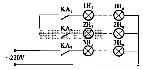
The described circuit employs a relay to control the operation of high-power lamps, which can be connected in parallel to increase total capacity. The relay serves as an electromechanical switch that opens and closes the circuit, enabling or disabling the lamp based on the control signal.
The key component influencing the flashing frequency is the capacitor, which works in conjunction with a resistor to form an RC timing circuit. When the capacitor charges and discharges, it determines the on-off cycle of the relay, thereby controlling the lamp's flashing rate. By selecting capacitors of different capacitances, the time constant of the RC circuit can be modified, resulting in varied flashing frequencies.
In this configuration, it is essential to ensure that the relay contacts can handle the total current drawn by the lamps. Additionally, protective components such as diodes may be included across the relay coil to prevent back EMF from damaging the control circuit when the relay is de-energized.
This simple yet effective design allows for versatile applications in decorative lighting, signaling, or any scenario where variable flashing is required. Proper selection of components and careful consideration of the relay's specifications will ensure reliable operation and longevity of the circuit.As a result of the relay control (several pairs of contacts, if more capacity is connected in parallel), so the lamp power can be large, the circuit is very simple, just change the capacitor capacitance, you can get a different flash frequency.
Related Circuits
The protected section of track can be of any desired length and does not need to be equal on both sides of the crossing. The circuit operates bidirectionally and can be linked with other grade crossing circuits to provide...
The amplification of this circuit is approximately 12,000 times, with a bandwidth ranging from 0.5 to 14 MHz. The input resistance is 700 ohms, while the output resistance is 35 ohms (measured at 5 MHz). The output noise level...
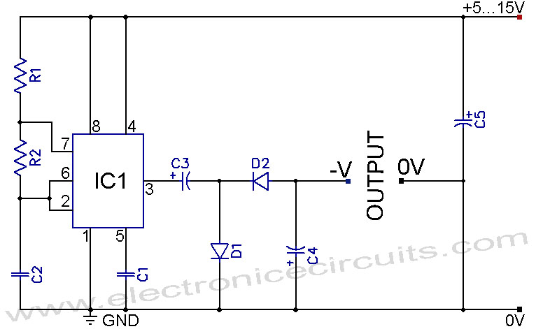
A 555 negative voltage power supply circuit can be created using a charge-pump configuration that incorporates a 555 timer, diodes, and additional components. The 555 timer is a versatile integrated circuit commonly used in various applications, including oscillators, timers, and...
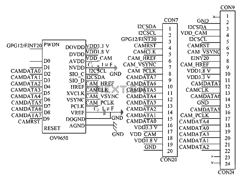
The circuit principle involves the OV9650 processor, which interfaces through three components: the SCCB interface, the data output interface, and the control interface. The SCCB interface is responsible for transferring initialization parameters from the processor's internal registers. It utilizes...
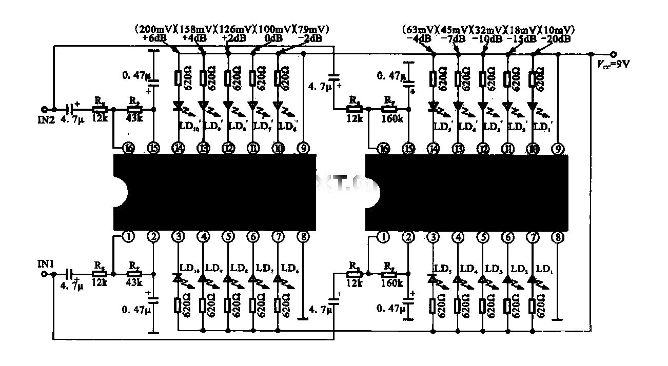
The circuit consists of dual drive integrated circuits (ICs) utilized in a 10 LED level meter configuration. The schematic features two TLM8101 driver ICs, which can be employed as alternatives. The 10 LED level meter circuit is designed to provide...
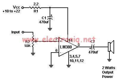
A simple audio amplifier can be designed using the LM380 along with a few external components. This amplifier features a wide supply voltage range, an input impedance of 150 kΩ, low distortion, and a current capability of 1.3 A. The...