
Simple 555 Switching Circuit Provides Negative Supply from Single Positive Supply

To generate a negative supply voltage from a single positive supply, a common approach is to utilize a charge pump circuit or a voltage inverter. These circuits can efficiently convert the positive voltage into a negative voltage suitable for operational amplifier applications.
A typical charge pump circuit consists of a capacitor, diodes, and a switching element (often a transistor or a dedicated IC). The operation involves charging the capacitor to the positive supply voltage and then reversing the polarity to create a negative output voltage. The switching frequency can be adjusted to optimize performance, balancing efficiency and ripple voltage.
For instance, in a basic charge pump configuration, the circuit can be designed with a 555 timer IC configured in astable mode to generate a square wave signal. This signal drives a transistor that switches the current through the capacitor, effectively inverting the voltage. The output can be further smoothed using an additional capacitor and a low-dropout (LDO) regulator to achieve a stable negative voltage supply.
In applications where low power consumption is critical, specialized ICs designed for negative voltage generation can be employed. These devices simplify the design process, often integrating the necessary components into a single package, thus reducing the overall footprint and component count.
This negative voltage supply is particularly useful in applications where operational amplifiers are used in inverting configurations or where signal processing requires both positive and negative voltage rails. It is essential to ensure that the generated negative voltage meets the specifications required by the operational amplifier to avoid distortion or damage to the circuit.If you need a negative supply for op-amp or just need negative bias voltage while operating from a single supply voltage (for battery operation for example),. 🔗 External reference
Related Circuits
This circuit illustrates a color sensor circuit diagram. The design is grounded in the principles of optics and digital electronics. The color sensor circuit typically employs a light-sensitive component, such as a photodiode or phototransistor, to detect and differentiate colors...
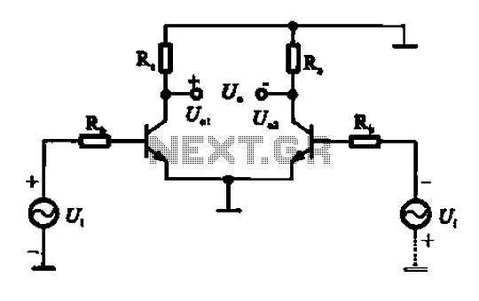
An amplifier circuit is designed to handle an assumed input consisting of two equal and opposite polarity signals, known as a differential mode signal. The two tube collector currents, Ic and IC7, are balanced in such a way that...
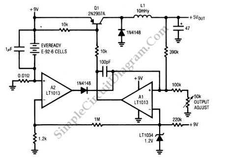
A circuit of a low-power switching regulator is illustrated in the schematic diagram below. This circuit can provide an output voltage of 5V from a 9V source. The efficiency... The low-power switching regulator circuit is designed to convert a higher...
The circuit of the unit is fairly simple, but is a bit irksome to set up. The reason is that obtaining matched FETs is not easy, so I had to make sure that the circuit would work with off-the-shelf...
This chapter provides detailed schematics of various power supplies suitable for use with common Ar/Kr ion tubes available to hobbyists in the surplus market. Included are examples of commercial designs (Omnichrome 150R and 532 head, Lexel 88 and head)...
This water level alarm circuit can be utilized as a water level indicator to monitor the desired water level in various applications, such as tanks, swimming pools, or any location where water is stored. The circuit is constructed using...