
simple self-powered circuit

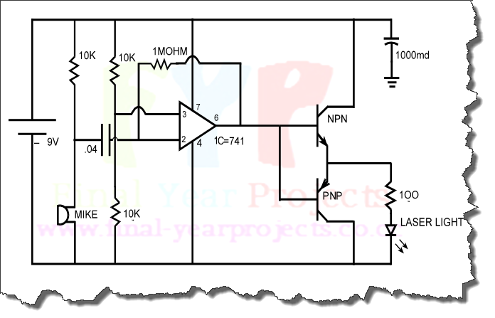
The circuit described operates on the principle of energy storage and self-sustaining operation. Initially, a twelve-volt battery is connected to the circuit, providing the necessary voltage and current to power a large diameter Light-Emitting Diode (LED). The LED serves as a visual indicator that the circuit is operational.
Upon powering the circuit, the LED lights up, indicating that current is flowing. The unique aspect of this circuit is its ability to maintain LED illumination even after the battery is disconnected. This phenomenon can be attributed to the incorporation of a capacitive or inductive element that stores energy when the circuit is powered.
When the battery is removed, the stored energy is released, allowing the LED to continue emitting light for a brief period. The duration of the LED's illumination depends on the capacitance or inductance used in the circuit, as well as the current draw of the LED itself.
The self-powering characteristic of this circuit challenges conventional electrical principles, as it suggests a form of perpetual energy that defies standard expectations of energy conservation. However, it is important to note that this circuit does not create energy; it merely utilizes stored energy, which will eventually deplete.
This circuit can serve as a fundamental educational tool for understanding basic electronic principles, including voltage, current, and energy storage. It also raises interesting discussions regarding circuit design and the limitations imposed by the laws of physics. Further exploration could involve experimenting with different energy storage components, such as capacitors or inductors, to observe variations in performance and LED illumination duration.This simple circuit is started running by connecting a twelve volt battery across the terminals, causing the large diameter Light-Emitting Diode to light up. When the battery is removed, the LED stays lit up because the circuit has become self-powering. While, at this scale, this is not a particularly useful project, it is an interesting one because conventional science says that it is quite impossible to do this.
If you decide to start some project, then whatever project you pick, the most important thing is that it should be one which interests you. You will notice that the projects suggested here generally have moving parts which make it easy to see how the device is operating.
The more difficult projects where there are no moving parts and meters need to be used can be left for a later time. If you decide to build something, then let me wish you good luck with your project. 🔗 External reference
Related Circuits
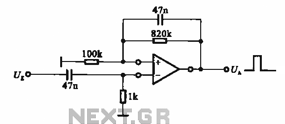
It demonstrates the use of various types of pulse signal generating circuits utilizing operational amplifiers. The circuit described involves the implementation of pulse signal generators using operational amplifiers (op-amps), which are versatile components frequently employed in analog electronics. These circuits...
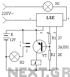
The device circuit operates as illustrated in Figure 11. Power outages are a common occurrence, but in certain situations, maintaining power is critical, such as during ongoing surgeries. The circuit employs a simple design that is fully automated. When...
The objective of this project is to design a circuit for an electronic infrared communication system, develop innovative ideas for implementing this circuit, and study the circuitry along with various components such as DTMF generators, DTMF decoders, operational amplifiers,...
This digital DIY tachometer for bicycles utilizes two reed switches to gather speed information. The reed switches are positioned near the wheel rim, where permanent magnets, attached to the wheel spokes, pass by and activate the switches. The speed...
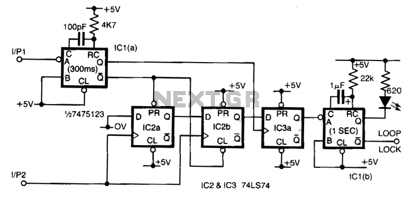
Input 1 functions as a gating period, during which a single rising edge on input 2 produces a logic 1 output. Any other input that indicates non-identical frequencies results in a logic 0 output. IC1a converts input 1 into...
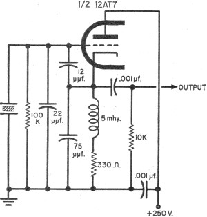
To update the fundamental oscillator circuits, simply replace the transistors with tubes. Alternatively, if one owns a vintage vacuum tube radio, it may be of interest to learn about historical practices. In general, the foundational principles of electronic circuits...