
Mini Voice Operated RelayCircuit
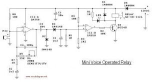
The voice-operated relay circuit typically consists of a microphone, an amplifier, a comparator, and a relay module. The microphone captures sound waves and converts them into electrical signals. These signals are then amplified to ensure they are strong enough for further processing.
The amplified signal is fed into a comparator circuit, which compares the input signal against a predefined threshold level. When the sound exceeds this threshold, the comparator output changes state, signaling the relay to activate. This activation allows the relay to close its contacts, thereby connecting the output to the power source or load.
The relay is a crucial component in this circuit, as it provides electrical isolation between the low-power sound detection circuit and the high-power load. It ensures that the circuit can safely control devices that require higher voltages or currents without risking damage to the sound detection components.
Additionally, the circuit may include a delay mechanism to prevent false triggering from transient sounds or noise. This can be implemented using a simple RC (resistor-capacitor) timing circuit or a more sophisticated microcontroller-based approach, depending on the desired complexity and reliability of the system.
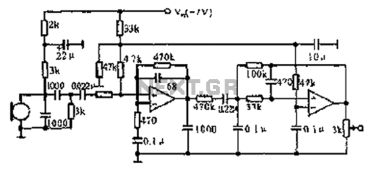
Overall, the voice-operated relay circuit is an effective solution for applications requiring sound-based control, such as automated lighting systems, remote switching, or interactive installations.This is the circuit diagram of a voice operated relay. It similar with sound activation switch circuit which will turn on and turn off (connect and disconnect) the switch depending on the sound input. The output switch of this circuit is act by a relay. 🔗 External reference
Related Circuits
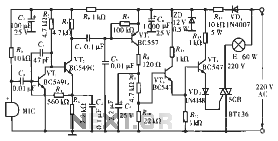
The circuit utilizes condenser microphones to detect sound and convert it into signal variations. This signal is then processed through directly coupled transistors VT1 and VT2, which form an amplification stage before being fed into a switching circuit. The...
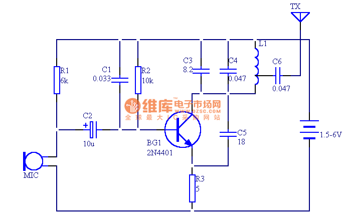
The circuit presented in this document utilizes 12 components to create a compact wireless FM microphone that operates with a stable frequency. The effective transmission range is approximately 30 meters, extending to over 100 meters when powered by a...
Input Amplifier Module: a low noise circuit equipped with a variable voltage-gain (10 - 100) pre-set, primarily intended as high quality microphone input, also suitable for low-level line input. High-quality modular design. 9V Battery powered - Very low current...
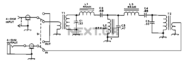
The circuit provides an 8-ohm output for connecting communication receivers and low-impedance speakers or headphones, featuring harmful interference suppression for continuous random voice transmission. The passband ranges from 55 to 2530 Hz with a 3 dB bandwidth. Inductors L1...
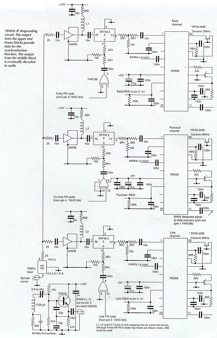
Until recently, spread spectrum techniques were primarily utilized in military applications. Their implementation in GPS and modern cellular phones is paving the way for various civil applications. This article, the first of two parts, explores the technology by detailing...
The CX9800 models of mobile phones and desktop PCs feature a high-performance voice processing circuit that compresses the amplitude and bandwidth of the microphone signal. This design enhances the sensitivity of the microphone and its adaptability to varying distances....
Warning: include(partials/cookie-banner.php): Failed to open stream: Permission denied in /var/www/html/nextgr/view-circuit.php on line 713
Warning: include(): Failed opening 'partials/cookie-banner.php' for inclusion (include_path='.:/usr/share/php') in /var/www/html/nextgr/view-circuit.php on line 713